
Home/Product ranges/Hydraulic hose reels for machinery
DEMAC rangeHydraulic hose reels for machinery
Compare models by number of hoses, their arrangement and the movement to follow. For a replacement, start from the full part number and existing installation.
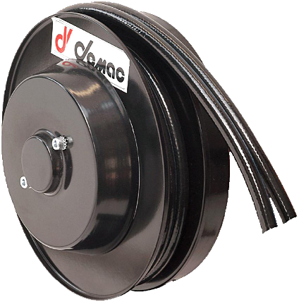
Go to hydraulic models
Four hoses: three configurations to compare
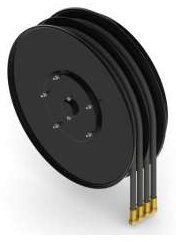
A4 Standard
Four hoses in two twin assemblies. Compare installation and travel.
View part numbers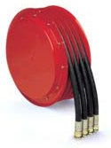
S4
Four separate hoses. Check each circuit and routing.
View part numbers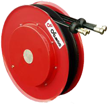
M4
Two independent springs for two separate movements.
View part numbersOther numbers of hoses
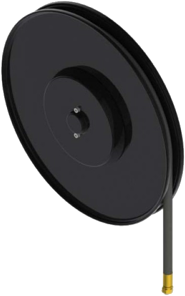
S1
One hydraulic hose, single-spiral winding.
View part numbersAG Standard
Twin hydraulic hoses.
View part numbers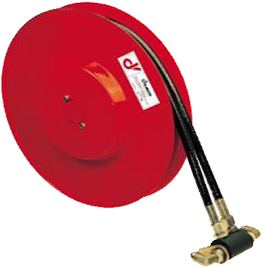
A2 Standard
Two separate hydraulic hoses.
View part numbers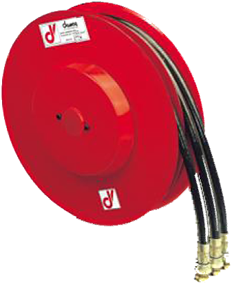
A3 Standard
Three hydraulic hoses.
View part numbers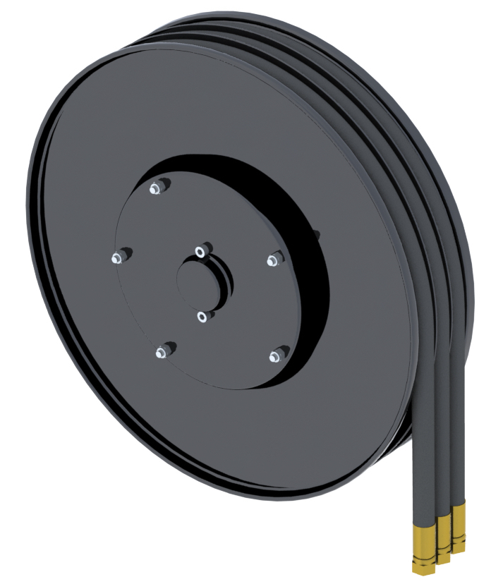
S3
Three separate hydraulic hoses.
View part numbers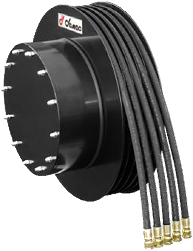
A5
Five hydraulic hoses.
View part numbers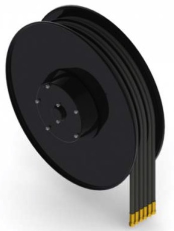
A6
Six hydraulic hoses.
View part numbersStart from your requirement
For a wall-mounted reel pulled by an operator, see instead workshop and fluid reels.
For four hoses, compare the A4, S4 and M4 configurations below: hose arrangement, movement to follow and overall dimensions are not interchangeable.
Choose the existing configuration, then consult the family part numbers. A photograph of the nameplate and connections can complete an incomplete part number.
Twin hoses
Two hoses in a twin configuration
AG, AG Compact, AG/F, AG.19, AG.25, LS
Separate hoses
Two separate hoses — different diameters or fluids
A2, A2/F, A2.19, A2.25, S3, S4
One hose
One single hose
S1, S1 Compact, M1, A1.25
Four hoses
Four hoses — attachment with two functions
A4, A4 Compact, S4, M4
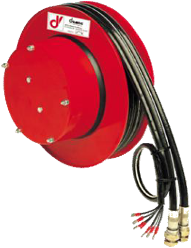
Hoses and cable
Hoses and electrical cable together
AG/E, A3/E, A4/E, A5/E, A6/E
Three, five or six hoses
Three, five or six hoses
A3, A5, A6
see below
The following criteria and comparison help check differences between the existing equipment and the proposed part number.
Families by number of lines
One line
- S1 Single Spiral — single-spiral winding, up to 18 m. The hose does not rub against itself: preferable for frequent cycles.
- S1 Compact — the smallest in the catalogue, 11 kg, up to 5,8 m.
- M1 Multi Spiral — multi-spiral, more compact for the same length, up to 26 m.
- A1.25 — up to 49 m and 135 l/min. For very long travel on a single line.
Two lines
- AG Standard — twin hose, sixteen sizes, up to 39 m. The broadest family in the catalogue.
- AG Compact — the reduced-size version.
- AG/F and A2/F — flat-flange mounting, without a projecting arm.
- A2 Standard — separate hoses, up to 22 m.
- AG.19, AG.25, A2.19, A2.25 — high flow rates and long lengths.
- LS/300 and LS/700 — with a locking latch. The LS/700 goes up to 700 bar.
Three lines
- A3 Standard — fourteen sizes, up to 37 m. Check diameters and lengths for the selected part number.
- S3 — separate hoses.
- A3.19 and A3.25 — high flow rates.
Four lines
- A4 Standard — two twin assemblies, fifteen sizes, up to 37 m.
- A4 Compact — the reduced-size version.
- S4 — four separate hoses; compare diameters, travel and dimensions with the A4.
- M4 — two independent springs. The two assemblies unwind separately: one reel for two components that do not move at the same time.
- A4.12 and A4.19 — high flow rates.
Four checks for a replacement
Start with mounting and available space when an existing bracket must be reused. Then check circuits and usable length against the part-number dimensions.
1. Mounting and available space
Record hole centres, bracket type, available width, mounting direction and connection positions. Compare the drawing for the part number, not just the visible flange diameter.
2. Number and arrangement of lines
Count moving circuits and identify twin or separate hoses. For four hoses, specify whether the assemblies follow the same movement or independent movements.
3. Flow rate, pressure and diameter
Record the data for each circuit. The .19 and .25 series are among the configurations to compare for high flow rates; check the combination offered for the selected diameter.
4. Usable length
Measure the travel to follow and check the usable length of the part number with its assembly. Length, hose diameter and overall dimensions must all be compatible at the same time.
Twin hoses or separate hoses
The hose configuration determines which arrangements to compare and the possibilities for replacing one line.
On a small screen, scroll the table horizontally to read all columns.
| Twin — AG, A4 families | Separate — A2, S3, S4 families | |
|---|---|---|
| Assembly construction | One-piece extruded profile | Independent hoses |
| Overall dimensions | More compact | Wider |
| Lines of different types | no | yes |
| Replacing one line | no, the whole assembly | yes |
| Diameters and pressures | identical on both lines | independent per line |
Twin hose winds flat without crossing or twisting, allowing a narrow drum. In return, damage to one line requires replacement of the whole assembly.
Points to check for the part number
Hose bend radius. A reel bends the hose continuously, and a hose cannot be wound tighter than its minimum radius. A 4SP in 3/4″ requires a radius of 300 mm, hence a drum of at least 600 mm. This is why four-braid hoses appear only on the larger sizes.
Permissible pressure of the assembly. The selected pressure must respect the limits of all components: reel, hoses and connections. Check the equipped assembly before selecting a pressure option.
Availability by size. Not every hose diameter is offered on every flange size. Check the part-number row corresponding to the required diameter and length.
Common configurations and options
- Right-hand or left-hand model — suffix
DorSin the part number. - Vertical downward travel — code
/VD, reinforced spring. - 400 bar configuration, when justified by the hose.
- ATEX II 2G configuration on request: compatibility and documents to be confirmed for the part number and location; see ATEX and custom-built enquiries.
- Standard range -20/+80 °C, -40/+80 °C configuration available.
What to send for a quotation
- For a replacement: full part number, photograph of the nameplate and views of the existing installation.
- Number of circuits and whether one can remain fixed.
- Internal diameter, flow rate and pressure of each circuit.
- Required usable length.
- Available space and achievable mounting hole centres.
- Connection direction and mounting position.
- Fluid, temperature and working environment.
Quotations and technical advice on request.