
Home/Product ranges/Combined hose and cable reels
DEMAC rangeCombined hose and cable reels
Choose a combined reel family according to hydraulic lines and electrical conductors. To replace equipment, record its full part number and mounting dimensions.
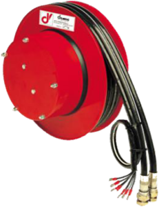
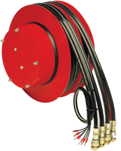
Choose the number of lines with cable
The five combined reels
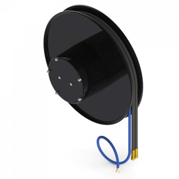

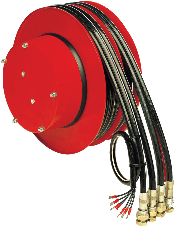
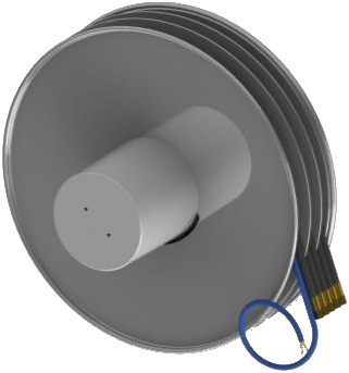
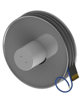
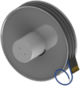
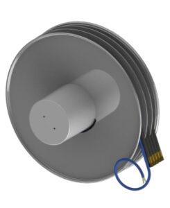
Identify the combined reel to replace
Before comparing families, record the elements that must remain compatible with the machine.
The hose/cable assembly. Number of hydraulic lines, hose diameter, number and cross-section of conductors; photograph any markings that remain legible.
The installation. Bracket, hole centres, available width, winding direction and connection positions.
Operating conditions. Travel, flow rates and pressures, voltage, current and signal type to transmit.
To replace the hose/cable assembly, identify the hose with integrated cable compatible with the reel and its connections.
If only one line is damaged, specify whether the enquiry concerns the complete hose/cable assembly or the equipped reel.
Compare length, flow rate and width
Compare part numbers at the selected diameter: family maximum values do not describe a single configuration.
Usable length. Check the length offered for the selected number of lines, diameter and flange size. A length available in one family cannot be transferred automatically to another.
Flow rate. The table distinguishes 40 l/min on the A3/E and A4/E from 30 l/min on the A5/E and A6/E. Check the part number corresponding to the machine circuits.
Width and mounting. Dimensions also depend on the number of conductors: compare the drawing of the complete configuration with the existing bracket before planning a substitution.
For four lines with cable in 1/2″, see the A4/E. Do not infer its configurations from the A4 Standard without cable.
The slip ring assembly
Electrical transmission is provided by a slip ring and brush assembly integrated into the hub. Maximum voltage 50 V, maximum current 5 A, with milliamp outputs and bus connections on request.
For a parts enquiry, include the slip ring assembly part number and connection diagram. A loss of continuity must be diagnosed before identifying the component to replace; work must follow the instructions for the part number.
When replacing equipment, also check signal compatibility and connections on the fixed and moving sides.
Read the part number
The code ends with /E followed by the number of conductors: /E2 for two, up to /E12 for twelve. The number of conductors determines reel width, and is listed in a dimensions table specific to each family.
Cable cross-section depends on hose diameter — 1 mm² with a 1/4″ hose, 1,5 mm² above that on the A6/E. And the twelve-conductor version is not offered with a 1/4″ hose, regardless of family.
What to send for a quotation
- For a replacement: full part number, photograph of the nameplate and views of the existing installation.
- Number of hydraulic lines, diameter and usable length.
- Flow rate and working pressure of each line.
- Number and cross-section of conductors : they determine the width.
- Voltage and current to transmit, and whether for power or signal.
- Any fieldbus, and which one.
- Available width and achievable mounting hole centres.
- Connection direction and mounting position.
Quotations and technical advice on request.