
Home/Applications and technical guides
Technical guideInstalling or replacing a DEMAC reel
This guide helps you prepare the work: identify the equipment, check its installation layout and obtain the correct manual. It does not replace the manufacturer’s procedure for the specific part number or the machine’s safety instructions.
Confirm the part number and documentation
Request the manual for my part number Browse the available catalogues and documents.
For a replacement, send the reel’s serial number, which is required to identify the unit to be replaced. It appears on the label; otherwise, see the illustrated locations on the Contact page. Also include a view of the installation and the full part number, if known. Request the manual and drawing for the part number and its version, particularly for the payout direction and any vertical downward travel.
A replacement must meet the machine’s requirements: usable travel, connections, mounting, guidance and operating conditions. Do not approve changes to the support or hose/cable bundle merely because the dimensions are similar.
What to check on the installation
Payout direction
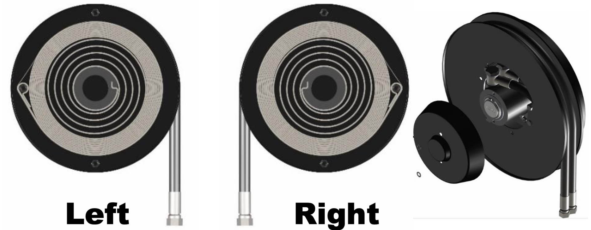
Compare the direction of the ordered model with that of the existing installation. Read the right- and left-hand designations in the documentation for the part number.
Support and fastenings
Check hole centres, drilling diameters, clearances and the support’s load capacity for the operating weight. One product family’s mounting template does not apply to all its sizes.
Travel and reserve length
Check the usable length and the reserve specified in the manual. Do not confuse total length with available travel; do not impose one reserve length on every series.
Hose/cable bundle guidance
Check alignment, routing over pulleys, friction and the minimum hose or cable bend radius. Use the layout drawing for the specific installation.
Spring, pressure and electrical power
Have qualified personnel carry out the work. The machine must be made safe in accordance with its procedures: isolate energy sources, depressurise the circuit and secure moving parts before starting work.
The spring may retain stored energy. Do not force a jammed drum or open the housing to change the direction or preload without the procedure and tools specified by the manufacturer.
Preload, number of turns, installation height and maintenance intervals depend on the equipment. Use the values stated in the manual and on the nameplate for your part number, not a general value found for another series.
For a workshop series with manual hose payout, follow the instructions for hose return and ratchet use. For a machine-mounted reel, check operation with the motion specified by the machine manufacturer.
Checks before returning to service
- Correct model, options and connections.
- Tightening and fastening in accordance with the applicable requirements.
- Routing without pinching or abnormal friction over the intended travel.
- Reserve and retraction in accordance with the manual; stops and guides in place.
- Hydraulic leak-tightness or electrical checks performed by competent personnel.
- Inspection and maintenance schedule suited to the manual and actual operating conditions.
Wear, leaks or faulty retraction require diagnosis before returning to service. When requesting a part, provide the reel’s full part number, not just the accessory name.
View guides, pulleys and accessories · Request a manual or drawing
Related parts and product families: guides and pulleys · CDL articulated guides · STP hose stops · combined hose and cable reels.
Read the direction of rotation and installation layout
On an AG twin-hose reel, the nameplate and manual identify the direction of rotation and preload limits. The illustrations below help locate the information to check before ordering a replacement or preparing an intervention.
A product-family illustration does not specify your reel’s settings
Reading example: DEMAC manual AGD 600.10.R7, edition 3/2026. Check the values, connections and procedure in the manual corresponding to your part number and serial number. These excerpts do not replace that complete manual or the machine’s instructions.
Preload: direction and number of turns are separate pieces of information
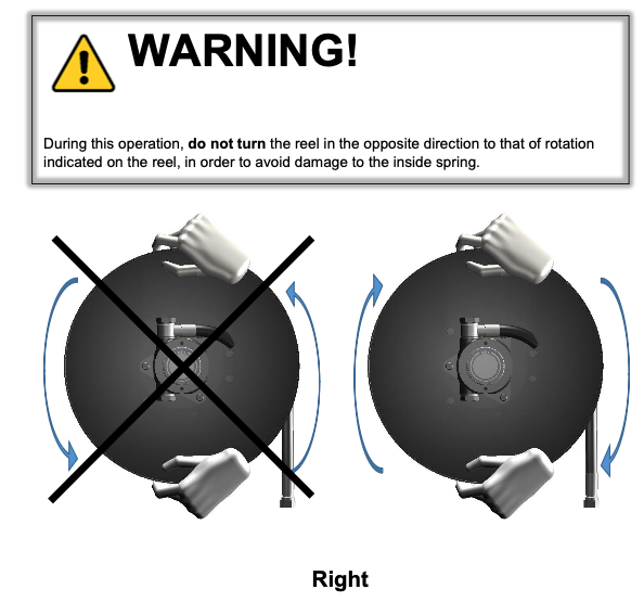
The illustration reminds you not to turn the reel in the opposite direction to that shown, as this may damage the spring. It does not specify the number of turns to apply. Read this number in the manual and on the nameplate for the relevant version; it cannot be inferred from the drum diameter or a photograph of a similar model.
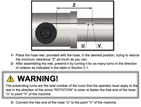
Telescopic crane: locate points U and V and dimension Z
In the example in the manual, U denotes the free end of the hose and V the connection point on the machine. Z is the clearance marked on the manufacturer’s drawing. To have us check an installation or replacement, include an overview and the dimensions of the existing installation.
Forklift truck: document the mast installation
To identify a replacement, photograph the reel, its mounting on the mast, the hose routing and connections. Clearances and alignment must be checked against the machine’s motion and the relevant manual; a dimension taken from another installation is not sufficient.
View forklift truck kits · View the complete manufacturer’s H/A/L usable-length diagram (PDF, page 5)
The catalogue’s H/A/L diagram helps prepare length measurements. It is neither a mounting manual nor a preload setting.
Right- or left-hand AG: confirm the version before replacement
Send the reel’s complete code and a photograph of its installation. The hose exit side and the direction marked on the device must match the installation. Mirroring a photograph or changing the hose routing is not enough to obtain an equivalent version.
The AG manual consulted includes a procedure for changing the direction. It involves, in particular, the spring and the internal hose routing: this is not a setting to improvise on the machine. For a replacement, have the suitable version confirmed before ordering.
To change the direction, request the complete procedure
Work on the spring is reserved for qualified personnel with the full procedure and suitable tools. The manual specifically requires attention to the condition of the spring retaining band; this band must never be removed or moved. Any modification to the equipment must be agreed with the manufacturer.
Faulty retraction, wear or leaks: prepare for diagnosis
The same symptom may have several causes. Before ordering a part, send the serial number, a photograph of the installation and the precise location of the fault. Do not increase preload to compensate for a blockage, and do not continue using equipment with a leak or abnormal retraction.
| What you observe | Useful information to send us |
|---|---|
| Uneven retraction or jammed drum | Part number, when the fault occurs and a view of the hose routing. Do not force the drum. |
| Hose coming off the drum | Photograph of the hose exit, guidance and readable nameplate information. |
| Localised hose wear | Photographs of the worn area and the alignment between the reel and the moving connection. |
| Hydraulic leak | Apparent location: hub, connection or hose. Do not search for a leak with your hand. |
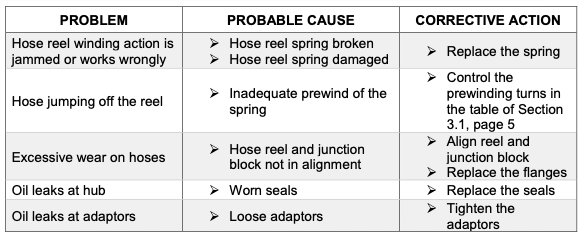
View the troubleshooting table in the AG manual
This table relates symptoms to possible causes. Its corrective actions require reading the manual’s Maintenance section and work by a qualified person; they do not constitute a remote diagnosis of your equipment.
DEMAC general catalogue by GEDO (PDF) · Documentation and manual requests
Commercial catalogues help identify product families and part numbers. They do not replace an installation and maintenance manual suited to the equipment.
Need to find a part number or identify a replacement?
Send the full part number if you know it. Otherwise, start with a legible photo of the nameplate, a view of the reel and its mountings, and the machine make and model. Include the specifications already available; we will clarify any additional checks with you.
Compatibility must be confirmed for the selected configuration before ordering.