DEMAC range · Quotations and technical advice on request

Home›Hydraulic hose reels for machinery›A6 reel — 6 hydraulic lines in three twin hoses

A6 reel — 6 hydraulic lines in three twin hoses

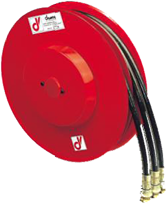
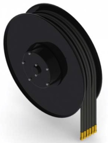
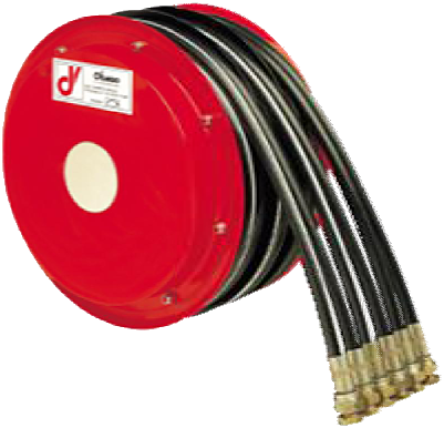
A6 reel with six hydraulic lines in three twin hoses, 40 l/min. Twelve sizes and 1.2 to 26.5 m usable length depending on the configuration, diameters from 1/4″ to 1/2″, right-hand or left-hand model.
Number of lines
6 hydraulic lines
Hose diameter
1/4" - DN 6 to 1/2" - DN 13
High pressure
Up to 400 bar
Material
Painted steel
A6 reel — 6 hydraulic lines in three twin hoses | DEMAC

Technical specifications

Technical specifications

Product type

Hose reel

Hose configuration

Twin hose

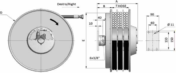
View front and side drawing (enlarge)
Number of lines

6 hydraulic lines

Flow rate

40 l/min

Application

High-pressure hydraulics, Mobile machinery and cranes

Rewind mechanism

Automatic (spring rewind)

Material

Painted steel

Pressure 300 bar, 400 bar
Hose diameter 1/4" - DN 6, 5/16" - DN 8, 3/8" - DN 10, 1/2" - DN 13
Length range Up to 15 m, 15 to 30 m
ATEX zone

On request — confirmation required

Hose type

B1, B2, SAE 100 R7, SAE 100 R8, T2

Maximum fluid temperature

80 °C

Equipment

Bare reel, Supplied with hoses

A6 reel with six hydraulic lines in three twin hoses, 40 l/min. Twelve sizes and 1.2 to 26.5 m usable length depending on the configuration, diameters from 1/4″ to 1/2″, right-hand or left-hand model.
Key features

  • Six hydraulic lines in three twin hoses.
  • 40 l/min; unwinding speed 30 m/min.
  • 12 sizes, flange diameters 295 to 720 mm.
  • Diameters 1/4″, 5/16″, 3/8″ and 1/2″.

Part number and replacement

A6D : right-hand model; A6S : left-hand model. The first sizes are named 295,320 and 340, not 296,321 or 341. The suffix XX specifies the hose type.

Options

  • 300 bar as standard; 400 bar optional.
  • -20/+80 °C; -40/+80 °C optional.
  • Vertical downward travel: /VD.
  • ATEX II 2G execution on request.

Sizes and technical data

Dimensions in millimetres; A = 285 mm and B = 107 mm for all rows. Weights are not given. The drawing shows 6 × 3/8″ and a mounting flange with Ø 11 mm holes, mounting centres 60 × 130 mm and overall dimensions 90 × 150 mm.

Model D (flange) E
A6D295 295 290
A6D320 325 272
A6D340 340 272
A6D370 370 322
A6D400 400 322
A6D420 420 322
A6D470 478 422
A6D520 520 422
A6D570 570 422
A6D600 620 532
A6D650 650 532
A6D700 720 532

Part numbers and lengths

Lengths in metres, with total and usable lengths kept separate. Tariff 152 lists R7, R8, B1, T2 and B2 according to diameter; all twelve sizes now include a 1/2″ row. The maximum usable length of 26.5 m applies to A6D700.06.XX in 1/4″.

Part number Ø Total length Usable length
A6D295.06.XX 1/4″ 3.0 2.7
A6D295.08.XX 5/16″ 2.3 2.0
A6D295.10.XX 3/8″ 2.3 2.0
A6D295.12.XX 1/2″ 1.5 1.2
A6D320.06.XX 1/4″ 4.0 3.7
A6D320.08.XX 5/16″ 3.2 2.9
A6D320.10.XX 3/8″ 3.3 3.0
A6D320.12.XX 1/2″ 2.5 2.2
A6D340.06.XX 1/4″ 5.0 4.7
A6D340.08.XX 5/16″ 4.2 3.9
A6D340.10.XX 3/8″ 4.0 3.7
A6D340.12.XX 1/2″ 2.5 2.2
A6D370.06.XX 1/4″ 6.0 5.7
A6D370.08.XX 5/16″ 5.3 5.0
A6D370.10.XX 3/8″ 4.5 4.2
A6D370.12.XX 1/2″ 3.5 3.2
A6D400.06.XX 1/4″ 7.3 7.0
A6D400.08.XX 5/16″ 6.5 6.2
A6D400.10.XX 3/8″ 5.6 5.3
A6D400.12.XX 1/2″ 4.5 4.2
A6D420.06.XX 1/4″ 8.6 8.1
A6D420.08.XX 5/16″ 8.0 7.5
A6D420.10.XX 3/8″ 6.7 6.2
A6D420.12.XX 1/2″ 4.7 4.2
A6D470.06.XX 1/4″ 11.5 11.0
A6D470.08.XX 5/16″ 10.0 9.5
A6D470.10.XX 3/8″ 9.5 9.0
A6D470.12.XX 1/2″ 7.5 7.0
A6D520.06.XX 1/4″ 14.5 14.0
A6D520.08.XX 5/16″ 12.5 12.0
A6D520.10.XX 3/8″ 11.2 10.7
A6D520.12.XX 1/2″ 9.0 8.5
A6D570.06.XX 1/4″ 17.5 17.0
A6D570.08.XX 5/16″ 15.5 15.0
A6D570.10.XX 3/8″ 13.5 13.0
A6D570.12.XX 1/2″ 10.7 10.2
A6D600.06.XX 1/4″ 21.0 20.5
A6D600.08.XX 5/16″ 17.0 16.5
A6D600.10.XX 3/8″ 16.0 15.5
A6D600.12.XX 1/2″ 12.5 12.0
A6D650.06.XX 1/4″ 22.5 22.0
A6D650.08.XX 5/16″ 19.5 19.0
A6D650.10.XX 3/8″ 17.5 17.0
A6D650.12.XX 1/2″ 14.5 14.0
A6D700.06.XX 1/4″ 27.0 26.5
A6D700.08.XX 5/16″ 22.0 21.5
A6D700.10.XX 3/8″ 20.0 19.5
A6D700.12.XX 1/2″ 16.0 15.5

Example: A6D420.10.XX denotes size 420, in 3/8″, with 6.2 m usable length. Confirm the hose type and connections for each circuit; for an unequipped version, specify ‘without hoses’.

The permissible pressure of the supplied assembly must remain within the limits of the reel, hose and connections. Specify the medium, its temperature, flow rate and working pressure to confirm the equipped part number; the pressure rating of the reel alone does not guarantee the rating of every hose combination.

Pressure ratings of the hoses alone

TU2 catalogue data: pressure ratings of the hose alone, in bar. These values are not the guaranteed pressure rating of the equipped reel. The final configuration must comply with the limits of all its components; the table below does not establish that every combination is available in every size.

Internal Ø Hose type Pressure rating of the hose alone (bar)
1/4″ R7 210
1/4″ B1 310
1/4″ R8 350
1/4″ T2 400
1/4″ B2 425
5/16″ R7 190
5/16″ B1 250
5/16″ R8 300
5/16″ T2 400
3/8″ R7 160
3/8″ B1 225
3/8″ R8 280
3/8″ T2 330
3/8″ B2 350

Preparing a replacement

To replace a reel, provide the full part number and a photo of the nameplate, together with the mounting details, right-hand/left-hand model, operating position, connections and usable length. Request the manual for the exact version before installation or any work on the reel.

For an A6 enquiry in 1/2″, state the usable length, hose type and connections for each of the six lines. See the DEMAC technical catalogues.

Unsure about the part number?

Tell us the number of lines, hose diameter, working pressure and flow rate, usable length and the machine to be equipped.

Request a quote

Product:

Enter your part number, quantity or required specifications. Fields marked * are required.

Enquiry type *
Your requirements *
If you know the part number, provide the full code and quantity. For a replacement, send the information available: serial number, a clear photo of the nameplate, and a view of the reel and its installation. The serial number is required for certain identification; if it cannot be found, submit your enquiry anyway and see the illustrated locations on the Contact page. For a new configuration, specify the number of hoses or cables, usable length and available technical data. Tell us what you know; we will help you complete the details.
Company
Name
Email address *
Telephone
Attach a file
Maximum file size: 10 MB
For a replacement, if possible attach a clear photo of the label showing the serial number, plus a view of the reel or its installation. If the number cannot be found, send the photos, drawing or part number available; your enquiry can be assessed and completed afterwards. Up to 3 files, maximum 10 MB per file.

Open the form on the Contact page

Call us