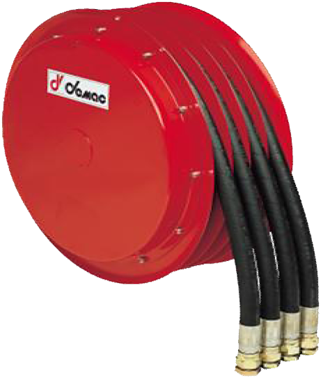
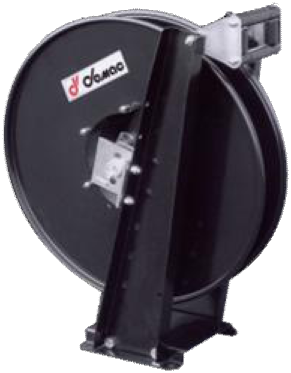
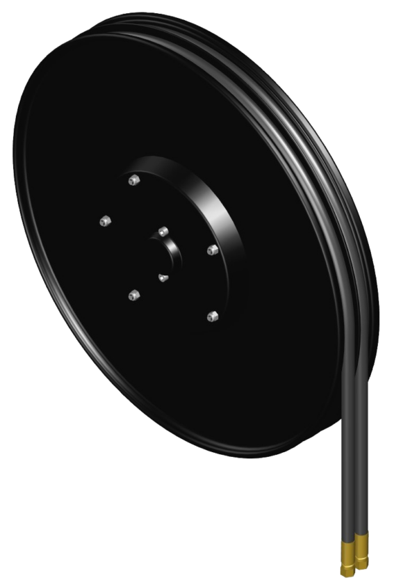
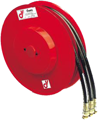
A3 Standard reel: three hydraulic lines in a triplex hose assembly, 40 l/min. Fourteen sizes and 1,2 to 37 m usable length depending on diameter; right-hand or left-hand models.
| Product type | Hose reel |
|---|---|
| Hose configuration | Triple hose |
| Number of lines | 3 hydraulic lines |
| Flow rate | 40 l/min |
| Application | High-pressure hydraulics, Mobile machinery and cranes |
| Rewind mechanism | Automatic (spring rewind) |
| Material | Painted steel |
| Pressure | 300 bar, 400 bar |
| Hose diameter | 1/4" - DN 6, 5/16" - DN 8, 3/8" - DN 10, 1/2" - DN 13 |
| Length range | Up to 15 m, 15 to 30 m, 30 to 50 m |
| ATEX zone | On request |
| Hose type | B1, B3, SAE 100 R8, T2 |
| Maximum fluid temperature | 80 °C |
| Equipment | Bare reel, Supplied with hoses |
| Technical drawings | View technical drawings |
The A3 Standard is a spring-return reel for three hydraulic lines in a triplex hose assembly. Fourteen sizes cover 1,2 to 37 m of usable length depending on the diameter and part number, with a maximum flow rate of 40 l/min. For a replacement, compare the complete hose assembly, travel and mounting drawing.
A3D: right-hand model; A3S: left-hand model. XX specifies B1, R8, T2 or B3 depending on the configuration. Retain the diameter code and full part number of the existing reel.
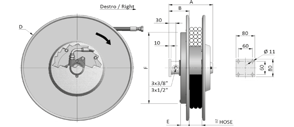
/VD.Dimensions in millimetres, weights without hoses. The second A/B values apply to 1/2″. Weights for sizes 800/900 are not specified. The drawing shows 3 × 3/8″ or 3 × 1/2″; PDF/STEP drawings on request.
| Model | A | B | D (reel side plate) | E | F | Weight without hoses |
|---|---|---|---|---|---|---|
| A3D296 | 185 / 250 | 87 / 127 | 295 | 37 | 272 | 16 kg |
| A3D321 | 185 / 250 | 87 / 127 | 325 | 37 | 272 | 17 kg |
| A3D341 | 185 / 250 | 87 / 127 | 340 | 37 | 272 | 18 kg |
| A3D370 | 185 / 250 | 87 / 127 | 370 | 37 | 272 | 18 kg |
| A3D400 | 185 / 250 | 87 / 127 | 400 | 47 | 272 | 19 kg |
| A3D420 | 185 / 250 | 87 / 127 | 420 | 47 | 322 | 22 kg |
| A3D470 | 198 / 250 | 97 / 127 | 478 | 47 | 322 | 24 kg |
| A3D520 | 198 / 250 | 97 / 127 | 520 | 47 | 322 | 28 kg |
| A3D570 | 198 / 250 | 97 / 127 | 570 | 47 | 422 | 32 kg |
| A3D600 | 198 / 250 | 97 / 127 | 620 | 47 | 422 | 38 kg |
| A3D650 | 198 / 250 | 97 / 127 | 650 | 47 | 422 | 44 kg |
| A3D700 | 198 / 250 | 97 / 127 | 720 | 57 | 422 | 50 kg |
| A3D800 | 198 / 250 | 97 / 127 | 820 | 57 | 532 | — |
| A3D900 | 198 / 250 | 97 / 127 | 920 | 57 | 532 | — |
Total and usable lengths in metres. 1/4″ is listed up to size 700; sizes 800/900 are shown in 5/16″, 3/8″ and 1/2″. The maximum usable length of 37 m applies to the A3D900.08.XX in 5/16″.
| Part number | Internal Ø | Total length | Usable length |
|---|---|---|---|
| A3D296.06.XX | 1/4″ | 3,0 | 2,7 |
| A3D296.08.XX | 5/16″ | 2,3 | 2,0 |
| A3D296.10.XX | 3/8″ | 2,3 | 2,0 |
| A3D296.12.XX | 1/2″ | 1,5 | 1,2 |
| A3D321.06.XX | 1/4″ | 4,0 | 3,7 |
| A3D321.08.XX | 5/16″ | 3,2 | 2,9 |
| A3D321.10.XX | 3/8″ | 3,3 | 3,0 |
| A3D321.12.XX | 1/2″ | 2,5 | 2,2 |
| A3D341.06.XX | 1/4″ | 5,0 | 4,7 |
| A3D341.08.XX | 5/16″ | 4,2 | 3,9 |
| A3D341.10.XX | 3/8″ | 4,0 | 3,7 |
| A3D341.12.XX | 1/2″ | 2,5 | 2,2 |
| A3D370.06.XX | 1/4″ | 6,0 | 5,7 |
| A3D370.08.XX | 5/16″ | 5,3 | 5,0 |
| A3D370.10.XX | 3/8″ | 4,5 | 4,2 |
| A3D370.12.XX | 1/2″ | 3,5 | 3,2 |
| A3D400.06.XX | 1/4″ | 7,3 | 7,0 |
| A3D400.08.XX | 5/16″ | 6,5 | 6,2 |
| A3D400.10.XX | 3/8″ | 5,6 | 5,3 |
| A3D400.12.XX | 1/2″ | 4,5 | 4,2 |
| A3D420.06.XX | 1/4″ | 8,6 | 8,1 |
| A3D420.08.XX | 5/16″ | 8,0 | 7,5 |
| A3D420.10.XX | 3/8″ | 6,7 | 6,2 |
| A3D420.12.XX | 1/2″ | 4,7 | 4,2 |
| A3D470.06.XX | 1/4″ | 11,5 | 11,0 |
| A3D470.08.XX | 5/16″ | 10,0 | 9,5 |
| A3D470.10.XX | 3/8″ | 9,5 | 9,0 |
| A3D470.12.XX | 1/2″ | 7,5 | 7,0 |
| A3D520.06.XX | 1/4″ | 14,5 | 14,0 |
| A3D520.08.XX | 5/16″ | 12,5 | 12,0 |
| A3D520.10.XX | 3/8″ | 11,2 | 10,7 |
| A3D520.12.XX | 1/2″ | 9,0 | 8,5 |
| A3D570.06.XX | 1/4″ | 17,5 | 17,0 |
| A3D570.08.XX | 5/16″ | 15,5 | 15,0 |
| A3D570.10.XX | 3/8″ | 13,5 | 13,0 |
| A3D570.12.XX | 1/2″ | 10,7 | 10,2 |
| A3D600.06.XX | 1/4″ | 21,0 | 20,5 |
| A3D600.08.XX | 5/16″ | 17,0 | 16,5 |
| A3D600.10.XX | 3/8″ | 16,0 | 15,5 |
| A3D600.12.XX | 1/2″ | 12,5 | 12,0 |
| A3D650.06.XX | 1/4″ | 22,5 | 22,0 |
| A3D650.08.XX | 5/16″ | 19,5 | 19,0 |
| A3D650.10.XX | 3/8″ | 17,5 | 17,0 |
| A3D650.12.XX | 1/2″ | 14,5 | 14,0 |
| A3D700.06.XX | 1/4″ | 27,0 | 26,5 |
| A3D700.08.XX | 5/16″ | 22,0 | 21,5 |
| A3D700.10.XX | 3/8″ | 20,0 | 19,5 |
| A3D700.12.XX | 1/2″ | 16,0 | 15,5 |
| A3D800.08.XX | 5/16″ | 30,0 | 29,0 |
| A3D800.10.XX | 3/8″ | 26,0 | 25,0 |
| A3D800.12.XX | 1/2″ | 21,0 | 20,0 |
| A3D900.08.XX | 5/16″ | 38,0 | 37,0 |
| A3D900.10.XX | 3/8″ | 34,0 | 33,0 |
| A3D900.12.XX | 1/2″ | 28,0 | 27,0 |
The size in the part number does not always match the actual reel side plate: the A3D600 measures 620 mm at D. The mounting flange drawing shows Ø 11 mm holes on a 60 mm square centre spacing with an 80 mm overall envelope. Confirm the orientation and connection before selecting a replacement.
The permissible pressure of the supplied assembly must remain within the limits of the reel, hose and connections. Specify the fluid, its temperature, the flow rate and the working pressure to confirm the hose-equipped part number; the pressure rating of the reel alone does not guarantee that of every hose combination.
Reference values from the TU3 catalogue: pressure ratings of the hose alone, in bar. These values are not the guaranteed pressure rating of the hose-equipped reel. The final configuration must remain within the limits of all its components; the table below does not establish that every combination is available for every size.
| Internal Ø | Hose type | Pressure rating of hose alone (bar) |
|---|---|---|
| 1/4″ | B1 | 310 |
| 5/16″ | B1 | 250 |
| 5/16″ | T2 | 400 |
| 3/8″ | B1 | 225 |
| 3/8″ | R8 | 280 |
| 3/8″ | T2 | 330 |
| 3/8″ | B3 | 420 |
| 1/2″ | B1 | 190 |
| 1/2″ | R8 | 245 |
| 1/2″ | T2 | 275 |
| 1/2″ | B3 | 350 |
To replace a reel, send the full part number and a photo of the nameplate, together with details of the mounting, right-hand/left-hand configuration, working position, fittings and usable length. Request the manual for the exact version before installation or any work on the reel.
The S3 uses three separate hoses and has its own lengths, particularly in 4SP. For diameters of 5/8″ or 3/4″, compare the A3.19; for 1″, consult the A3.25. See the DEMAC technical catalogues.


Tell us the number of lines, hose diameter, working pressure and flow rate, usable length and the machine to be equipped.

DEMAC by GEDO
The DEMAC range for business customers. Technical advice, replacement and custom configurations.
+33 (0)4 86 68 48 31 contact@gedo.fr565 avenue du Prado
13008 Marseille
Offices only, by appointment.
Request a quoteGEDO FRANCE — SASU with share capital of 30 000 € — RCS Marseille 494 021 678 — Business customers only.