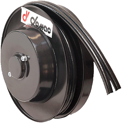
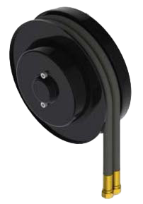
The AG Standard is a spring-driven hose reel for two hydraulic lines in a twin hose. Its 16 sizes cover usable lengths from 1.2 to 39 m depending on the part number, diameter and hose type. For replacement, compare the full code and mounting drawing of the existing reel.
Key features
- Two hydraulic lines in a twin hose.
- Maximum flow rate: 40 l/min.
- Maximum unwinding speed: 30 m/min.
- 16 sizes, flange diameters from 295 to 1 000 mm.
Part number and replacement
AGD : right-hand model; AGS : left-hand model. The suffix XX identifies the hose type. Attach a photo of the nameplate and serial number, together with the installation to be replaced.
Options
- 300 bar as standard; 400 bar optional.
- -20/+80 °C; -40/+80 °C optional.
- Vertical downward travel:
/VD.
- ATEX II 2G execution on request.
Sizes and dimensions
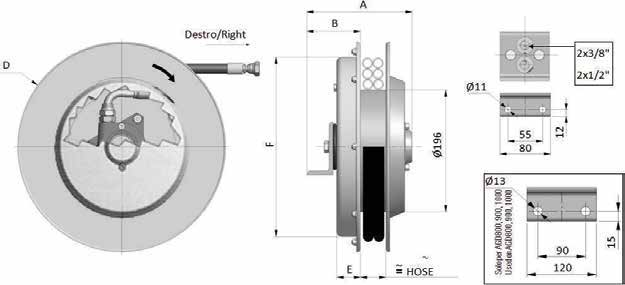
Dimensions A, B, D, E and F from the manufacturer’s drawing are in millimetres; weights are without hose. The size in the part number does not always match the actual flange diameter.
| Model |
A |
B |
D (flange) |
E |
F |
Weight without hose |
| AGD296 |
161 |
75 |
295 |
35 |
291 |
13 kg |
| AGD321 |
161 |
82 |
325 |
37 |
272 |
14 kg |
| AGD341 |
161 |
82 |
340 |
37 |
272 |
14 kg |
| AGD370 |
161 |
82 |
370 |
37 |
272 |
14.5 kg |
| AGD400 |
161 |
82 |
400 |
47 |
322 |
15 kg |
| AGD420 |
161 |
82 |
420 |
47 |
322 |
19 kg |
| AGD470 |
161 |
82 |
478 |
47 |
322 |
21 kg |
| AGD520 |
171 |
92 |
520 |
47 |
422 |
23 kg |
| AGD570 |
171 |
92 |
570 |
47 |
422 |
28 kg |
| AGD600 |
171 |
92 |
620 |
47 |
422 |
34 kg |
| AGD650 |
181 |
102 |
650 |
57 |
422 |
37 kg |
| AGD700 |
181 |
102 |
720 |
57 |
532 |
40 kg |
| AGD800 |
226 |
122 |
820 |
67 |
532 |
47 kg |
| AGD900 |
226 |
122 |
920 |
67 |
532 |
60 kg |
| AGD950 |
232 |
126 |
950 |
67 |
687 |
70 kg |
| AGD1000 |
232 |
126 |
1000 |
67 |
687 |
75 kg |
The mounting drawing shows Ø 11 mm holes with 55/80 mm dimensions, and a bracket with Ø 13 mm holes and 90/120 mm dimensions for sizes 800, 900, 950 and 1000. Check the exact drawing, connections and overall dimensions before substitution. Technical PDF and STEP drawings on request.
Part numbers and lengths
Lengths in metres. Distinguish the total fitted length from the usable length available for travel. The data sheet lists types R7, R8, B1, B2 and T2.
| Part number |
Internal Ø |
Total length |
Usable length |
| AGD296.06.XX |
1/4″ |
3.0 |
2.7 |
| AGD296.08.XX |
5/16″ |
2.3 |
2.0 |
| AGD296.10.XX |
3/8″ |
2.3 |
2.0 |
| AGD296.12.XX |
1/2″ |
1.5 |
1.2 |
| AGD321.06.XX |
1/4″ |
4.0 |
3.7 |
| AGD321.08.XX |
5/16″ |
3.2 |
2.9 |
| AGD321.10.XX |
3/8″ |
3.3 |
3.0 |
| AGD321.12.XX |
1/2″ |
2.5 |
2.2 |
| AGD341.06.XX |
1/4″ |
5.0 |
4.7 |
| AGD341.08.XX |
5/16″ |
4.2 |
3.9 |
| AGD341.10.XX |
3/8″ |
4.0 |
3.7 |
| AGD341.12.XX |
1/2″ |
2.5 |
2.2 |
| AGD370.06.XX |
1/4″ |
6.0 |
5.7 |
| AGD370.08.XX |
5/16″ |
5.3 |
5.0 |
| AGD370.10.XX |
3/8″ |
4.5 |
4.2 |
| AGD370.12.XX |
1/2″ |
3.5 |
3.2 |
| AGD400.06.XX |
1/4″ |
7.3 |
7.0 |
| AGD400.08.XX |
5/16″ |
6.5 |
6.2 |
| AGD400.10.XX |
3/8″ |
5.6 |
5.3 |
| AGD400.12.XX |
1/2″ |
4.5 |
4.2 |
| AGD420.06.XX |
1/4″ |
8.6 |
8.1 |
| AGD420.08.XX |
5/16″ |
8.0 |
7.5 |
| AGD420.10.XX |
3/8″ |
6.7 |
6.2 |
| AGD420.12.XX |
1/2″ |
4.7 |
4.2 |
| AGD470.06.XX |
1/4″ |
11.5 |
11.0 |
| AGD470.08.XX |
5/16″ |
10.0 |
9.5 |
| AGD470.10.XX |
3/8″ |
9.5 |
9.0 |
| AGD470.12.XX |
1/2″ |
7.5 |
7.0 |
| AGD520.06.XX |
1/4″ |
14.5 |
14.0 |
| AGD520.08.XX |
5/16″ |
12.5 |
12.0 |
| AGD520.10.XX |
3/8″ |
11.2 |
10.7 |
| AGD520.12.XX |
1/2″ |
9.0 |
8.5 |
| AGD570.06.XX |
1/4″ |
17.5 |
17.0 |
| AGD570.08.XX |
5/16″ |
15.5 |
15.0 |
| AGD570.10.XX |
3/8″ |
13.5 |
13.0 |
| AGD570.12.XX |
1/2″ |
10.7 |
10.2 |
| AGD600.06.XX |
1/4″ |
21.0 |
20.5 |
| AGD600.08.XX |
5/16″ |
17.0 |
16.5 |
| AGD600.10.XX |
3/8″ |
16.0 |
15.5 |
| AGD600.12.XX |
1/2″ |
12.5 |
12.0 |
| AGD650.06.XX |
1/4″ |
22.5 |
22.0 |
| AGD650.08.XX |
5/16″ |
19.5 |
19.0 |
| AGD650.10.XX |
3/8″ |
17.5 |
17.0 |
| AGD650.12.XX |
1/2″ |
14.5 |
14.0 |
| AGD700.06.XX |
1/4″ |
27.0 |
26.5 |
| AGD700.08.XX |
5/16″ |
22.0 |
21.5 |
| AGD700.10.XX |
3/8″ |
20.0 |
19.5 |
| AGD700.12.XX |
1/2″ |
16.0 |
15.5 |
| AGD800.08.XX |
5/16″ |
30.0 |
29.0 |
| AGD800.10.XX |
3/8″ |
26.0 |
25.0 |
| AGD800.12.XX |
1/2″ |
21.0 |
20.0 |
| AGD900.08.XX |
5/16″ |
38.0 |
37.0 |
| AGD900.10.XX |
3/8″ |
34.0 |
33.0 |
| AGD900.12.XX |
1/2″ |
28.0 |
27.0 |
| AGD950.10.XX |
3/8″ |
37.0 |
36.0 |
| AGD950.12.XX |
1/2″ |
31.0 |
30.0 |
| AGD1000.10.XX |
3/8″ |
40.0 |
39.0 |
| AGD1000.12.XX |
1/2″ |
35.0 |
34.0 |
XX must be replaced with the hose type confirmed for the selected diameter and size, for example AGD296.06.R7. For an unequipped version, explicitly request supply without hose; the generic suffix is not sufficient to define the order.
The permissible pressure of the supplied assembly must remain within the limits of the reel, hose and connections. Specify the medium, its temperature, flow rate and working pressure to confirm the equipped part number; the pressure rating of the reel alone does not guarantee the rating of every hose combination.
Pressure ratings of the hoses alone
TU2 catalogue data: pressure ratings of the hose alone, in bar. These values are not the guaranteed pressure rating of the equipped reel. The final configuration must comply with the limits of all its components; the table below does not establish that every combination is available in every size.
| Internal Ø |
Hose type |
Pressure rating of the hose alone (bar) |
| 1/4″ |
R7 |
210 |
| 1/4″ |
B1 |
310 |
| 1/4″ |
R8 |
350 |
| 1/4″ |
T2 |
400 |
| 1/4″ |
B2 |
425 |
| 5/16″ |
R7 |
190 |
| 5/16″ |
B1 |
250 |
| 5/16″ |
R8 |
300 |
| 5/16″ |
T2 |
400 |
| 3/8″ |
R7 |
160 |
| 3/8″ |
B1 |
225 |
| 3/8″ |
R8 |
280 |
| 3/8″ |
T2 |
330 |
| 3/8″ |
B2 |
350 |
| 1/2″ |
B1 |
190 |
| 1/2″ |
R8 |
245 |
| 1/2″ |
T2 |
260 |
| 1/2″ |
B2 |
310 |
Preparing a replacement
To replace a reel, provide the full part number and a photo of the nameplate, together with the mounting details, right-hand/left-hand model, operating position, connections and usable length. Request the manual for the exact version before installation or any work on the reel.
The AGD600.10.R7 manual calls for checking the alignment of the reel and connection block, observing the indicated direction and following the requirements specific to the part number. The spring prewinding and hose pressure values in a particular manual do not apply to the whole range.
For a smaller overall size, compare the AG Compact (30 l/min); for two separate hoses, compare the A2. Find the drawings and DEMAC technical catalogues.