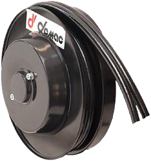
Application example
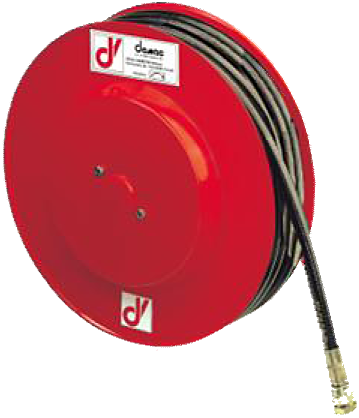
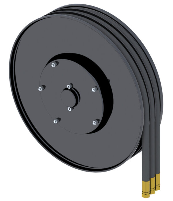
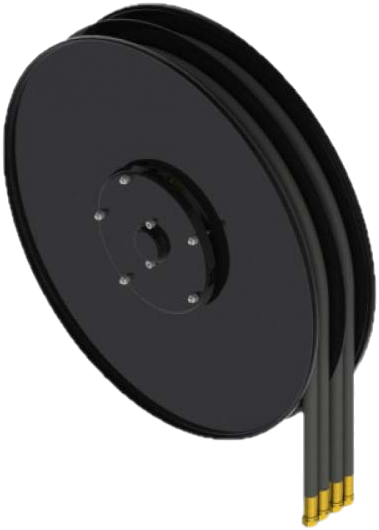
On a telescopic boom, the hose pays out as the boom extends. The spring rewinds it as the boom retracts. The M1 winds the hose in several layers, reducing the space needed for a given hose length. It is suitable for applications with moderate cycling.
M1 multi-spiral reel for one hose. Ten sizes with published data, from 1/4″ to 1″; lengths vary with 1SC-LL, T2 or B1, up to 29.5 m usable. 1″ version on request.
Key features
- One line, multi-spiral winding.
- 10 sizes with published data, side plates from 295 to 820 mm.
- 1SC-LL, T2 or B1 hoses.
- Usable length = total length minus 0.5 m.
Part number and replacement
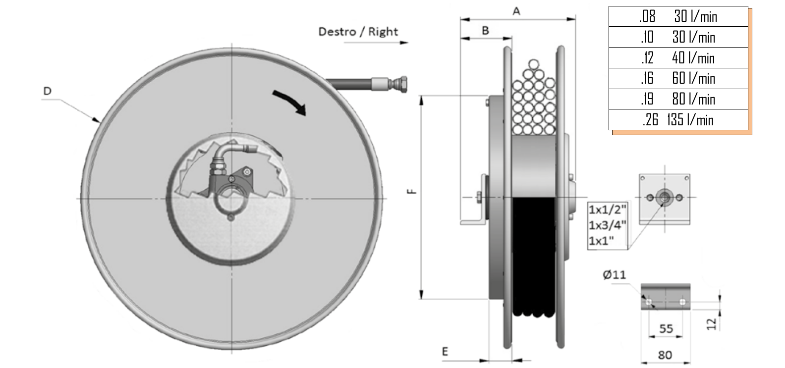
M1D denotes the right-hand model and M1S the left-hand model. The diameter code and hose type XX are needed to read the correct capacity.
Options
- 300 bar as standard; 400 bar optional.
- -20/+80 °C; -40/+80 °C optional.
- Vertical downward travel:
/VD.
- ATEX II 2G execution on request.
Sizes and technical data
Published dimensions in millimetres, weights not provided. The manufacturer’s flow-rate table also mentions large-diameter codes, but their part numbers and lengths are not detailed here. The flow rate for code .06 is not specified.
| Right-hand model |
A |
B |
D: side plate |
E |
F |
| M1D296 |
182 |
92 |
295 |
47 |
292 |
| M1D321 |
182 |
92 |
325 |
47 |
292 |
| M1D341 |
182 |
92 |
340 |
47 |
292 |
| M1D370 |
182 |
92 |
370 |
47 |
292 |
| M1D470 |
193 |
92 |
478 |
47 |
422 |
| M1D520 |
213 |
92 |
520 |
47 |
422 |
| M1D570 |
213 |
92 |
570 |
47 |
422 |
| M1D600 |
225 |
112 |
620 |
57 |
532 |
| M1D700 |
245 |
102 |
720 |
48 |
422 / 532 |
| M1D800 |
245 / 260 |
102 / 122 |
820 |
48 / 68 |
422 / 532 |
| Code |
Internal Ø |
Maximum flow rate |
| .08 |
5/16″ |
30 l/min |
| .10 |
3/8″ |
30 l/min |
| .12 |
1/2″ |
40 l/min |
| .16 |
5/8″ |
60 l/min |
| .19 |
3/4″ |
80 l/min |
| .26 |
1″ |
135 l/min |
Part numbers and lengths
TOTAL lengths in metres for 1SC-LL, T2 and B1. Usable length = table value minus 0.5 m. The maximum published value is 30 m total, or 29.5 m usable, for M1D800.10.XX with 1SC-LL.
| Part number |
Ø |
1SC-LL |
T2 |
B1 |
| M1D296.06.XX |
1/4″ |
4.7 |
3.5 |
5.5 |
| M1D321.06.XX |
1/4″ |
5.0 |
4.7 |
6.0 |
| M1D321.08.XX |
5/16″ |
4.5 |
4.0 |
5.0 |
| M1D321.10.XX |
3/8″ |
4.5 |
3.0 |
4.5 |
| M1D341.06.XX |
1/4″ |
5.5 |
5.0 |
6.0 |
| M1D341.08.XX |
5/16″ |
4.7 |
4.7 |
5.5 |
| M1D341.10.XX |
3/8″ |
4.7 |
4.5 |
5.0 |
| M1D370.06.XX |
1/4″ |
7.0 |
6.0 |
10.0 |
| M1D370.08.XX |
5/16″ |
7.0 |
5.5 |
9.0 |
| M1D370.10.XX |
3/8″ |
6.0 |
5.0 |
9.0 |
| M1D470.06.XX |
1/4″ |
15.5 |
14.5 |
16.0 |
| M1D470.08.XX |
5/16″ |
14.5 |
13.5 |
15.5 |
| M1D470.10.XX |
3/8″ |
13.5 |
12.5 |
15.0 |
| M1D520.06.XX |
1/4″ |
21.0 |
21.0 |
22.5 |
| M1D520.08.XX |
5/16″ |
16.5 |
15.0 |
21.5 |
| M1D520.10.XX |
3/8″ |
15.5 |
14.0 |
21.5 |
| M1D520.12.XX |
1/2″ |
13.5 |
11.5 |
17.5 |
| M1D570.08.XX |
5/16″ |
17.5 |
17.5 |
18.5 |
| M1D570.10.XX |
3/8″ |
17.0 |
17.0 |
17.5 |
| M1D570.12.XX |
1/2″ |
15.5 |
14.5 |
19.5 |
| M1D600.08.XX |
5/16″ |
20.5 |
20.5 |
26.0 |
| M1D600.10.XX |
3/8″ |
20.5 |
20.5 |
26.0 |
| M1D600.12.XX |
1/2″ |
20.5 |
20.5 |
26.0 |
| M1D700.12.XX |
1/2″ |
24.5 |
24.5 |
23.5 |
| M1D700.19.XX |
3/4″ |
19.0 |
19.0 |
— |
| M1D800.10.XX |
3/8″ |
30.0 |
29.0 |
28.5 |
| M1D800.12.XX |
1/2″ |
27.5 |
27.5 |
29.0 |
| M1D800.26.XX |
1″ |
19.0 |
— |
— |
1″ version on request: M1D800.26.XX. The M1D700 and M1D800 rows have published values in tariff 152; M1D400 is not a capacity row and has not been added.
Comparison at the same diameter: M1D600.12.XX has 20.5 m total length with 1SC-LL/T2, or 20 m usable; with B1, 26 m total gives 25.5 m usable. The published flow rate for .12 is 40 l/min.
The permissible pressure of the supplied assembly must respect the limits of the reel, hose and connections. Specify the fluid, its temperature, the flow rate and working pressure to validate the equipped part number; the pressure rating of the reel alone does not guarantee that of every hose combination.
Pressure ratings of hoses alone
TU1 catalogue reference data: pressure ratings of the hose alone, in bar. These values are not the guaranteed pressure rating of the equipped reel. The final configuration must respect the limits of all its components; the table below does not establish that every combination is available in every size.
| Internal Ø |
Hose type |
Pressure rating of hose alone (bar) |
| 1/4″ |
1SC-LL |
250 |
| 1/4″ |
B1 |
310 |
| 1/4″ |
T2 |
400 |
| 5/16″ |
1SC-LL |
250 |
| 5/16″ |
B1 |
250 |
| 5/16″ |
T2 |
400 |
| 3/8″ |
1SC-LL |
250 |
| 3/8″ |
B1 |
225 |
| 3/8″ |
T2 |
330 |
| 1/2″ |
1SC-LL |
200 |
| 1/2″ |
B1 |
190 |
| 1/2″ |
T2 |
260 |
| 3/4″ |
1SC-LL |
150 |
| 3/4″ |
T2 |
150 |
| 1″ |
1SC-LL |
110 |
Preparing a replacement
To replace a reel, send the full part number and a photograph of the nameplate, mounting details, right/left-hand version, working position, fittings and usable length. Request the manual for the exact version before installation or servicing.
Compare the single-spiral S1 and A1.25 against the usable length, diameter and mounting of the existing unit. The overall maximum of 135 l/min in the box does not apply to the 1/4″ to 1/2″ models listed in the table. See the DEMAC technical catalogues.