
Home/Applications/Telehandlers
Part number and configurationReels for telehandlers
To find a part number or replace a telehandler reel, send a photograph of the nameplate and installation. Compare four-hose configurations, two-hose versions and combined hose and cable reels against the specifications of the boom and attachment circuit.
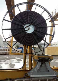
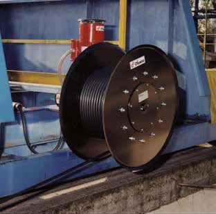
Four hoses, two hoses or combined hose/cable assembly
Choose a link by configuration. For four hoses with electrical cable, also see A4/E. Compare four-hose solutions.
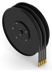
A4 Standard — four lines in twin hoses
A4 Standard reel with four lines in two twin hoses: 15 sizes, usable length from 2 to 37 m, maximum flow rate 30 l/min. Right-hand or left-hand model.
View part numbers
S4 — four separate hoses
S4 reel: four separate hydraulic hoses, 40 l/min, 12 sizes and 1,1 to 22 m usable length. Diameters 1/4″ to 1/2″, specific 4SP lengths.
View part numbers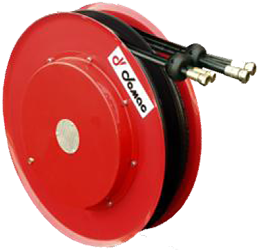
M4 — two independent hose assemblies
M4 reel with four lines in two twin hoses: two independent external springs, 40 l/min and 3,2 to 26,5 m usable length depending on configuration.
View part numbers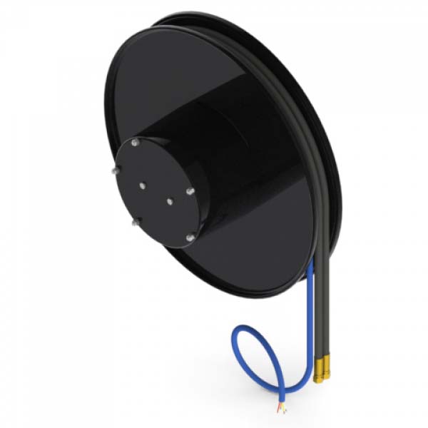
AG/E — two lines and cable
AG/E: 2 hydraulic hoses and one electrical cable. Diameter, usable length, conductors and mounting depend on the part number; identification on request.
View part numbers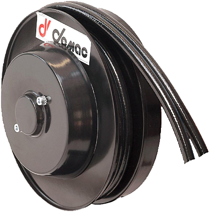
AG Standard — two lines in a twin hose
AG Standard reel: two lines in a twin hose, 40 l/min, 16 sizes and 1,2 to 39 m usable length depending on configuration. Right-hand or left-hand model.
View part numbers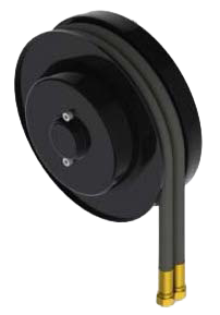
AG Compact — two lines in a twin hose
AG Compact reel: two lines in a twin hose, 30 l/min, 6 sizes and 1,3 to 5,7 m usable length depending on configuration. Right-hand or left-hand model.
View part numbers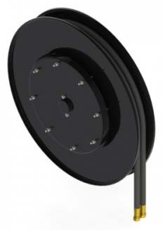
AG.19 — two lines, high flow rate
AG.19 reel: two lines in a twin hose, 80 l/min, 5/8″ B3 or 3/4″ HDH. Ten sizes and up to 27,5 m usable length depending on configuration.
View part numbersInstallation-related comparison points
A4 : Four hoses, two twin hoses; supply two hydraulic functions.
M4 : Four hoses, two assemblies; two hose assemblies with independent movements.
AG/E : Two hoses and electrical cable; specify hydraulic lines and electrical contacts.
AG Standard : Two lines, twin hose; hydraulic supply to the attachment.
AG Compact : Two lines, limited space; check travel and available dimensions.
AG.19 : Two lines, high flow rate; specify flow rate, pressure and diameter.
Start from the existing part number
Include the complete nameplate, a view of the reel on the machine and photographs of mountings, fittings and guides. Specify the components you wish to retain.
If the part number is illegible, record the hole centres and hole diameters, reel diameter and width, outlet direction and hose markings. The machine brand complements this information but does not establish equivalence on its own.
Configuration data
See the information to record
Hoses and cable
Number of hoses, type, diameter and fittings; electrical contacts and any signal.
Travel and guidance
Travel of the hose/cable assembly, end positions and routing on the boom.
Hydraulic circuit
Flow rate, pressure and fluid for the lines concerned.
Overall dimensions
Available dimensions, mountings, outlet direction and environment.
Document the mounting points
See the information to record
Guidance
Photograph the retained guides and pulleys, their positions and routing.
Drum and hose
Include the drum dimensions and hose part number to compare the configuration.
Outlet direction
Indicate the current outlet direction on the photographs. Any work must follow the applicable instructions.
Identify an LR sensor
If your enquiry also concerns an LR length and inclination sensor, record its part number, travel and signal. This component must be identified separately from the hydraulic reel.
Prepare your enquiry
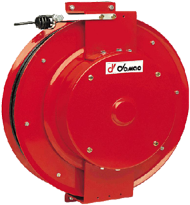
For a replacement, start with a legible photograph of the nameplate and a view of the installation. Add the information available below; identify anything still to be confirmed.
- Photograph of the nameplate, part number and quantity.
- Machine model, attachment and views of the installation.
- Travel of the hose/cable assembly, number of hoses and circuit specifications.
- Fittings, mountings, overall dimensions and outlet direction.
- Electrical contacts, signals and special requirements.