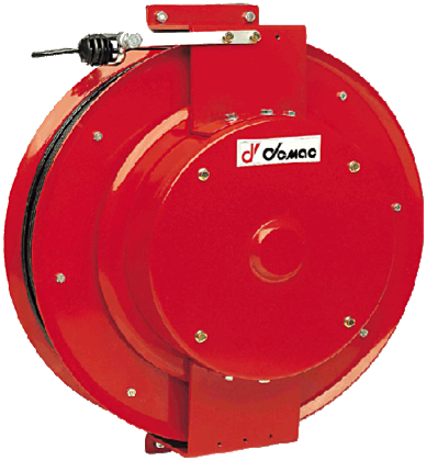
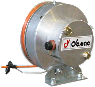
LR series: travel from 10 to 50 m depending on the cable. Ten measurement configurations, with one or two length sensors and, depending on suffix, inclination measurement. IP 65.
Part number / replacement
Record the full code and suffixes, quantity and existing connections; a nameplate photograph is useful. For a configuration, specify travel, required output and mounting.
Options
Outputs in volts, milliamperes or CANbus depending on suffix. The catalogue offers model/O layout and a -40 to +80 °C configuration.
Installation and operation
Maximum cable speed: 30 m/min; IP 65; standard temperature -20 to +60 °C, with a -40 to +80 °C configuration stated as available.
Stated electrical link limits: 50 V, 1 A. Sensor power supply is specified separately by suffix.
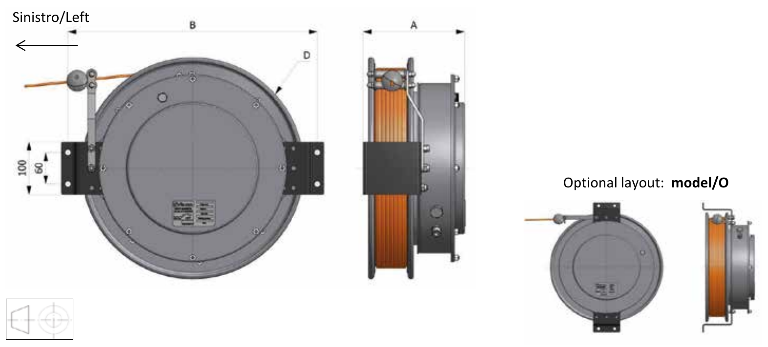
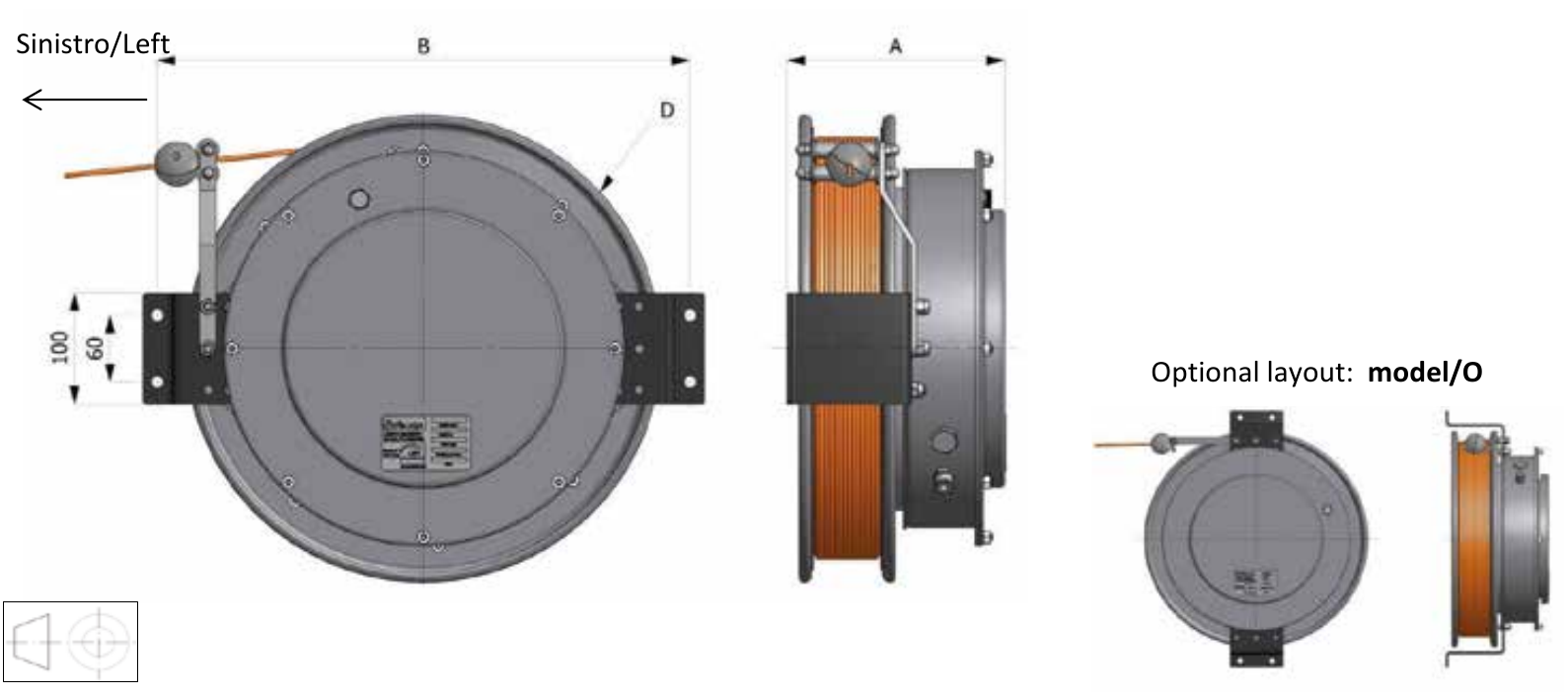
Left-hand version shown; alternative model/O layout. Check the mounting drawing and cable direction.
The sensor counts and accuracy figures in the table do not validate a safety function or compatibility with the controller.
For your enquiry
Full part number, suffixes and quantity; a nameplate photograph for a replacement.
Travel to be measured, available space and mounting.
Number of measurements, required output, power supply and connection diagram.
Accuracy and environmental requirements; presence of an electrical link and machine data.
Suffixes .1PV, .1PA, .2PV and .2PA are specified with length linearity of 0,25 %. Versions with inclination measurement: range 0–360°. CANbus versions .1PIB and .2PIB specify 7,5 Hz and 10–1 000 kbit/s.
Complete table of mechanical models
The 17 entries from pages 69 and 71 are grouped here: dimensions in millimetres, travel in metres. Replace X with the measurement suffix selected in the preceding table.
Poles
Cable
Ø cable
Travel
Model
A
B
D
Mass
0
Steel wire rope
1,5
20
LR 320.20.X
222
400
320
14 kg
0
Steel wire rope
1,5
30
LR 420.30.X
222
473
420
20 kg
3
3xAWG25 screened
3,8
20
LR 320.032520.X
222
400
320
15 kg
3
3xAWG25 screened
3,8
32
LR 420.032532.X
222
473
420
21 kg
3
3xAWG25 screened
3,8
40
LR 420.032540.X
222
473
420
21 kg
3
3xAWG25 screened
3,8
50
LR 520.032550.X
271
570
520
25 kg
5
4xAWG26 screened
4,0
20
LR 320.052520.X
222
400
320
16 kg
5
4xAWG26 screened
4,0
32
LR 420.052532.X
222
473
420
22 kg
5
4xAWG26 screened
4,0
40
LR 420.052540.X
222
473
420
22 kg
5
4xAWG26 screened
4,0
50
LR 520.052550.X
271
570
520
25 kg
7
7x0,34 screened
6,3
10
LR 320.073410.X
222
400
320
17 kg
7
7x0,34 screened
6,3
30
LR 420.073432.X
222
473
420
23 kg
7
7x0,34 screened
6,3
40
LR 520.073440.X
271
570
520
26 kg
12
12x0,5 screened
10,7
12
LR 420.120512.X
253
498
420
22 kg
12
12x0,5 screened
10,7
15
LR 420.120515.X
253
498
420
22 kg
12
12x0,5 screened
10,7
20
LR 420.120520.X
253
498
420
22 kg
12
12x1,5 screened
15,5
23
LR 520.121523.X
325
596
520
29 kg
The 7x0,34 mm², 30 m entry bears code LR 420.073432.X. The five-pole column is associated with the 4×AWG26 screened cable. These details are reproduced as published and should be confirmed against the connection diagram.