Home/Applications/Motorised reels
Part number and configurationMotorised reels: part number and configuration
To replace a motorised reel or define new equipment, include the part number, cable or hose data and movement specifications. Selection covers the complete motor, gearbox, slip ring assembly and drum, with the planned power supply and controls.
Go to motorised families
Motorised cable — torque motor
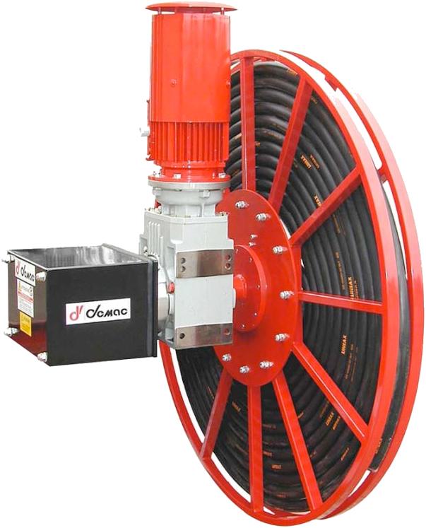
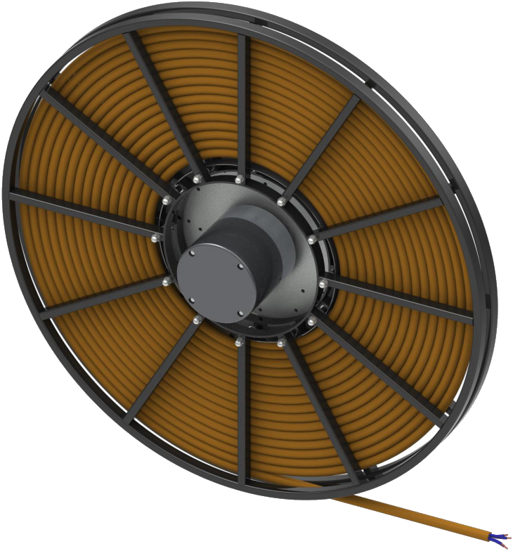
DEMAC motorised cable reel with torque motor. Single-spiral or random winding, cable and slip ring assembly depending on configuration. Provide the full part number or installation data with your enquiry.
View part numbers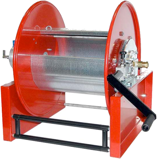
9871 — motorised hose reel for rescue services
DEMAC 9871 motorised-rewind reel for rescue vehicles, anti-rotation lock and manual rewind. Specify hose and drive configuration.
View part numbersSelection data for both motorised families
| Family | Configuration | Data to specify |
|---|---|---|
| Motorised cable reel | Cable reel with motor drive | Cable, contacts, travel, speed and power supply. |
| Type 9871 | Motorised hose reel for the relevant applications | Fluid, hose, circuit, travel and integration conditions. |
Identify the assembly to replace
Photograph the reel nameplate and, where separate, the motor and slip ring assembly nameplates. Add a view of the drum, guides and connections.
For a new configuration, state what has already been defined: cable or hose, travel, installation position and available power supply. Identify existing components to retain.
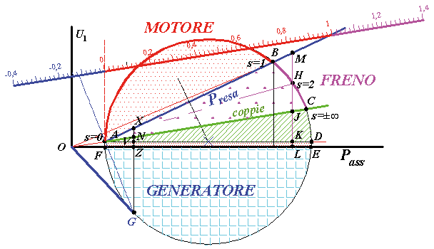
Torque motor operating curve
Components to configure
See the information to record
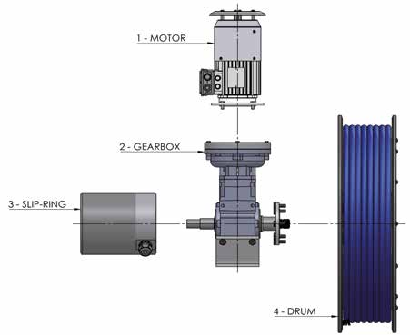
Motor and gearbox
The motorised catalogue describes a torque-motor and gearbox system. The configuration depends on the required movement and hose/cable assembly to wind.
Slip ring assembly
Specify power and signal contacts, voltages and currents, and the protocols concerned.
Drum
Cable or hose length, diameter and mass are part of the sizing data.
Specify power supply and controls
See the information to record
Include power supply specifications, planned controls and machine operating requirements. Connections and adjustments are defined using the documents for the selected equipment.
If your enquiry concerns the 9871 series, also specify the required manual-rewind functions and existing version.
Movement data
Travel and installation position
Length to wind, installation height and hose/cable routing.
Speed and acceleration
Machine movement data and operating cycle.
Cable or hose
Diameters, mass per unit length, permissible tensile load and available electrical or hydraulic specifications.
Environment
Indoor or outdoor, temperatures and marine environment or other constraints.
Compare with a spring-driven solution
See the information to record
The CR1200 has spring return: it is not a motorised reel. Check the part number and electrical and mechanical specifications.
If the drive has not yet been selected, send the same travel, hose/cable and movement data to compare solutions. Length alone does not determine the choice.
The LCR is an additional starting point for a spring-driven configuration. For guides and installation documents, see the installation information page relevant to your enquiry.
An enquiry requiring locking
See the information to record
For use with manual unwinding and locking, the 500 series is another family to identify. Specify the intended operating method and cable specifications; do not compare it with motorised reels by length alone.
ATEX requirement
If the installation is in a classified zone, include the specifications and required documents. The ATEX page lists the information to provide. Feasibility and the configuration of a special build still need to be confirmed.
Prepare your enquiry
For a replacement, start with a legible photograph of the nameplate and a view of the installation. Add the information available below; identify anything still to be confirmed.
- Reel, motor and slip ring assembly nameplates; part number and quantity.
- Cable or hose: diameter, mass and operating specifications.
- Travel, speed, acceleration and operating cycle.
- Available power supply and planned controls.
- Power and signal contacts, voltages and currents.
- Drawings, overall dimensions and ambient conditions.