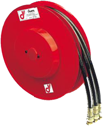
A4 Standard reel with four hydraulic lines in two twin hoses: 15 sizes, usable length from 2 to 37 m, maximum flow rate 30 l/min. Right-hand or left-hand model.
| Product type | Hose reel |
|---|---|
| Hose configuration | Twin hose |
| Number of lines | 4 hydraulic lines |
| Flow rate | 30 l/min |
| Usable travel | From 2 to 37 m depending on diameter and part number |
| Application | Forklift truck, High-pressure hydraulics, Mobile machinery and cranes |
| Rewind mechanism | Automatic (spring rewind) |
| Material | Painted steel |
| Pressure | 300 bar, 400 bar |
| ATEX zone | On request — confirmation required |
| Maximum fluid temperature | 80 °C |
| Equipment | Bare reel, Supplied with hoses |
| Hose diameter | 1/4" - DN 6, 5/16" - DN 8, 3/8" - DN 10 |
| Hose type | B1, B2, SAE 100 R7, SAE 100 R8, T2 |
| Technical drawings | View technical drawings |
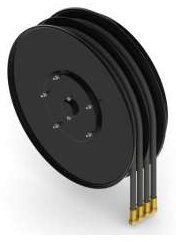
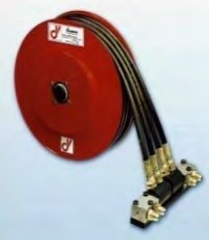
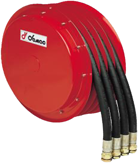
The A4 Standard supplies four hydraulic lines in two twin hoses, with automatic spring return. To replace a reel or specify a new installation, start with the existing part number or the combination of hose diameter and usable travel.
Find your hose diameter, then a usable travel that covers the actual movement. These values are for shortlisting a size; they do not confirm compatibility on their own. The model orientation, flow rate, pressure and mounting still need to be checked.
| Right-hand model | 1/4″ | 5/16″ | 3/8″ |
|---|---|---|---|
| A4D296 | 2.7 | 2.0 | 2.0 |
| A4D321 | 3.7 | 2.9 | 3.0 |
| A4D341 | 4.7 | 3.9 | 3.7 |
| A4D370 | 5.7 | 5.0 | 4.2 |
| A4D400 | 7.0 | 6.2 | 5.3 |
| A4D420 | 8.1 | 7.5 | 6.2 |
| A4D470 | 11.0 | 9.5 | 9.0 |
| A4D520 | 14.0 | 12.0 | 10.7 |
| A4D570 | 17.0 | 15.0 | 13.0 |
| A4D600 | 20.5 | 16.5 | 15.5 |
| A4D650 | 22.0 | 19.0 | 17.0 |
| A4D700 | 26.5 | 21.5 | 19.5 |
| A4D800 | — | 29.0 | 25.0 |
| A4D850 | — | 32.5 | 30.0 |
| A4D900 | — | 37.0 | 33.0 |
How to read the table: the values are usable lengths in metres. ‘—’ means this combination is not listed in the catalogue; no extrapolation is made. 1/2″ is not offered in this A4 Standard table.
Example: in 3/8″, the A4D520 offers 10.7 m usable length. The corresponding row is A4D520.10.XX ; the hose and connections still need to be specified.
All part numbers below remain visible on this product page. The usable travel comes before the total hose length to avoid confusion between them.
Jump to: 1/4″ part numbers · 5/16″ part numbers · 3/8″ part numbers.
A4D = right-hand model; A4S = left-hand model. The codes .06, .08 and .10 correspond to diameters 1/4″, 5/16″ and 3/8″ respectively. The suffix XX denotes the hose type to be confirmed, not a part number for supply without hoses.
| Right-hand version | Left-hand version | Usable travel (m) | Total hose length (m) |
|---|---|---|---|
A4D296.06.XX |
A4S296.06.XX |
2.7 | 3.0 |
A4D321.06.XX |
A4S321.06.XX |
3.7 | 4.0 |
A4D341.06.XX |
A4S341.06.XX |
4.7 | 5.0 |
A4D370.06.XX |
A4S370.06.XX |
5.7 | 6.0 |
A4D400.06.XX |
A4S400.06.XX |
7.0 | 7.3 |
A4D420.06.XX |
A4S420.06.XX |
8.1 | 8.6 |
A4D470.06.XX |
A4S470.06.XX |
11.0 | 11.5 |
A4D520.06.XX |
A4S520.06.XX |
14.0 | 14.5 |
A4D570.06.XX |
A4S570.06.XX |
17.0 | 17.5 |
A4D600.06.XX |
A4S600.06.XX |
20.5 | 21.0 |
A4D650.06.XX |
A4S650.06.XX |
22.0 | 22.5 |
A4D700.06.XX |
A4S700.06.XX |
26.5 | 27.0 |
| Right-hand version | Left-hand version | Usable travel (m) | Total hose length (m) |
|---|---|---|---|
A4D296.08.XX |
A4S296.08.XX |
2.0 | 2.3 |
A4D321.08.XX |
A4S321.08.XX |
2.9 | 3.2 |
A4D341.08.XX |
A4S341.08.XX |
3.9 | 4.2 |
A4D370.08.XX |
A4S370.08.XX |
5.0 | 5.3 |
A4D400.08.XX |
A4S400.08.XX |
6.2 | 6.5 |
A4D420.08.XX |
A4S420.08.XX |
7.5 | 8.0 |
A4D470.08.XX |
A4S470.08.XX |
9.5 | 10.0 |
A4D520.08.XX |
A4S520.08.XX |
12.0 | 12.5 |
A4D570.08.XX |
A4S570.08.XX |
15.0 | 15.5 |
A4D600.08.XX |
A4S600.08.XX |
16.5 | 17.0 |
A4D650.08.XX |
A4S650.08.XX |
19.0 | 19.5 |
A4D700.08.XX |
A4S700.08.XX |
21.5 | 22.0 |
A4D800.08.XX |
A4S800.08.XX |
29.0 | 30.0 |
A4D850.08.XX |
A4S850.08.XX |
32.5 | 33.5 |
A4D900.08.XX |
A4S900.08.XX |
37.0 | 38.0 |
| Right-hand version | Left-hand version | Usable travel (m) | Total hose length (m) |
|---|---|---|---|
A4D296.10.XX |
A4S296.10.XX |
2.0 | 2.3 |
A4D321.10.XX |
A4S321.10.XX |
3.0 | 3.3 |
A4D341.10.XX |
A4S341.10.XX |
3.7 | 4.0 |
A4D370.10.XX |
A4S370.10.XX |
4.2 | 4.5 |
A4D400.10.XX |
A4S400.10.XX |
5.3 | 5.6 |
A4D420.10.XX |
A4S420.10.XX |
6.2 | 6.7 |
A4D470.10.XX |
A4S470.10.XX |
9.0 | 9.5 |
A4D520.10.XX |
A4S520.10.XX |
10.7 | 11.2 |
A4D570.10.XX |
A4S570.10.XX |
13.0 | 13.5 |
A4D600.10.XX |
A4S600.10.XX |
15.5 | 16.0 |
A4D650.10.XX |
A4S650.10.XX |
17.0 | 17.5 |
A4D700.10.XX |
A4S700.10.XX |
19.5 | 20.0 |
A4D800.10.XX |
A4S800.10.XX |
25.0 | 26.0 |
A4D850.10.XX |
A4S850.10.XX |
30.0 | 31.0 |
A4D900.10.XX |
A4S900.10.XX |
33.0 | 34.0 |
The codes in the left-hand-version column are derived from the manufacturer’s convention: prefix A4S instead of A4D, without changing the other elements. The suffix XX still needs to be completed with the confirmed hose type. For an unequipped unit, explicitly state ‘without hoses’ in the enquiry. R7, R8, B1, B2 and T2 constructions appear in the manufacturer’s data sheet; their availability must be confirmed for the selected part number.
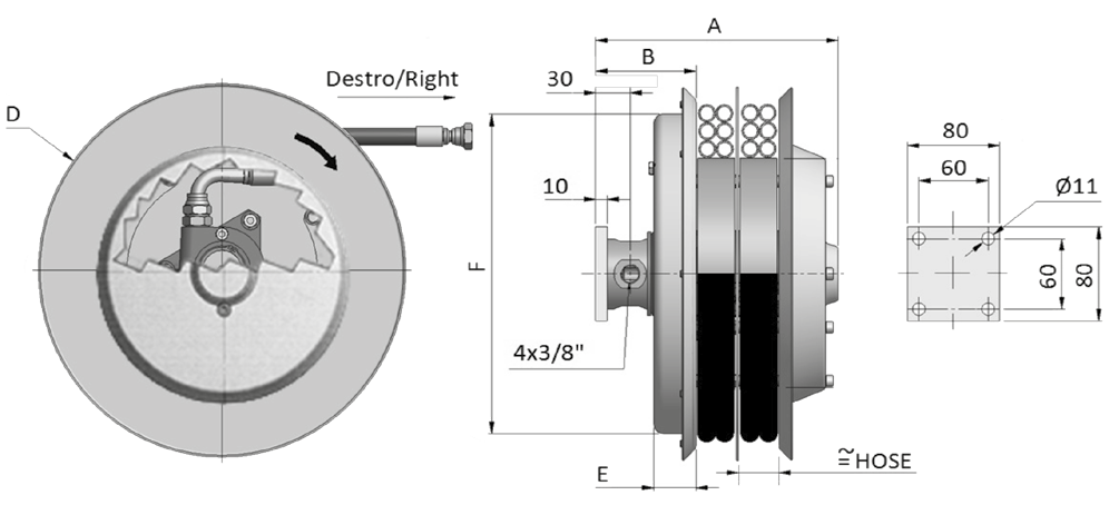
Before replacement, compare the complete drawing with the existing installation. The size code does not always indicate the actual flange diameter: the flange of the A4D600 has a diameter of 620 mm. Dimensions A, B, D, E and F refer to the manufacturer’s drawing on pages 15–16 of the general catalogue.
| Right-hand model | A | B | D: flange | E | F | Weight (kg) |
|---|---|---|---|---|---|---|
| A4D296 | 212 | 90 | 295 | 37 | 291 | 16 |
| A4D321 | 212 | 90 | 325 | 37 | 272 | 17 |
| A4D341 | 212 | 90 | 340 | 37 | 272 | 18 |
| A4D370 | 212 | 90 | 370 | 37 | 272 | 18 |
| A4D400 | 212 | 90 | 400 | 47 | 272 | 19 |
| A4D420 | 222 | 100 | 420 | 47 | 322 | 22 |
| A4D470 | 222 | 100 | 478 | 47 | 322 | 24 |
| A4D520 | 222 | 100 | 520 | 47 | 422 | 28 |
| A4D570 | 222 | 100 | 570 | 47 | 422 | 32 |
| A4D600 | 222 | 100 | 620 | 47 | 422 | 38 |
| A4D650 | 222 | 100 | 650 | 47 | 422 | 44 |
| A4D700 | 222 | 100 | 720 | 47 | 532 | 50 |
| A4D800 | 252 | 129 | 820 | 67 | 532 | 70 |
| A4D850 | 252 | 129 | 850 | 67 | 532 | 80 |
| A4D900 | 252 | 129 | 920 | 67 | 532 | 90 |
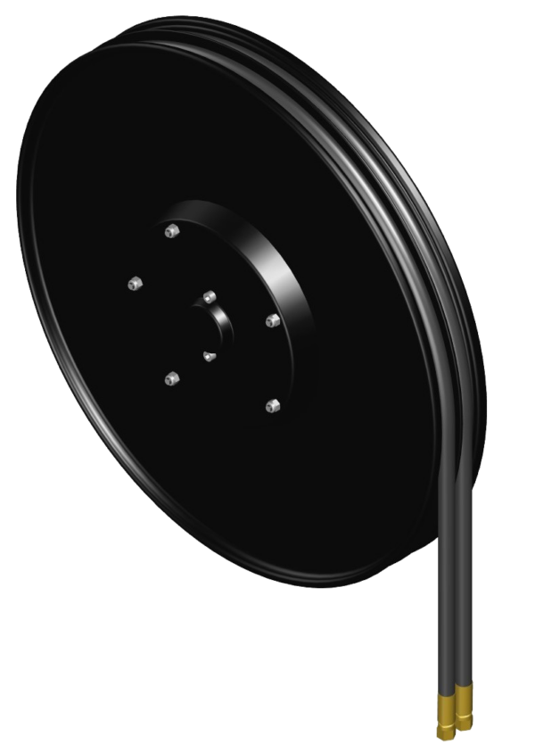
The drawing shows 4 × 3/8″ connections and Ø 11 mm holes, with mounting dimensions of 60 and 80 mm. Also compare the connection positions and guiding arrangement. Technical PDF and STEP drawings are available from the manufacturer on request.
Find the drawing in the DEMAC technical catalogues or attach a photo of the installation to your quote request.
300 bar as standard and 400 bar optional are the limits stated for the reel. The permissible pressure of the equipped assembly must respect the component with the lowest limit. The table below concerns the hoses only; it guarantees neither the assembly pressure rating nor the availability of all combinations.
| Internal Ø | Hose type | Hose alone (bar) |
|---|---|---|
| 1/4″ | R7 | 210 |
| 1/4″ | B1 | 310 |
| 1/4″ | R8 | 350 |
| 1/4″ | T2 | 400 |
| 1/4″ | B2 | 425 |
| 5/16″ | R7 | 190 |
| 5/16″ | B1 | 250 |
| 5/16″ | R8 | 300 |
| 5/16″ | T2 | 400 |
| 3/8″ | R7 | 160 |
| 3/8″ | B1 | 225 |
| 3/8″ | R8 | 280 |
| 3/8″ | T2 | 330 |
| 3/8″ | B2 | 350 |
/VD.Request the manual matching the part number and year of the reel. The A4D470.10.B1 manual calls for checking alignment with the connection block, the indicated direction and the limits of the fitted hose. The nameplate and serial number identify the version and parts; spring prewinding parameters from another version must not be reused.
The A4 Standard does not cover every four-line requirement. For four separate hoses, compare the S4. For two independent external springs, compare the M4. For a diameter or flow rate not covered, consider the A4.12 and A4.19 against the requirements of each circuit.
Changing product family requires checking the hose configuration, travel and mountings; the number of lines or cycles is not sufficient to establish equivalence. Include the existing part number or your requirements in the quote request so the selection can be confirmed.
Tell us the number of lines, hose diameter, working pressure and flow rate, usable length and the machine to be equipped.
DEMAC by GEDO
DEMAC products for business customers. Technical advice and replacement assistance on request.
+33 (0)4 86 68 48 31 contact@gedo.fr565 avenue du Prado
13008 Marseille
Offices only, by appointment.
Request a quoteGEDO FRANCE — SASU with share capital of 30 000 € — RCS Marseille 494 021 678 — Business customers only.