DEMAC range · Quotations and technical advice on request

HomeHydraulic hose reels for machineryS1 Single Spiral reel — 1 hydraulic hose

S1 Single Spiral reel — 1 hydraulic hose

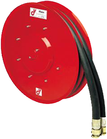
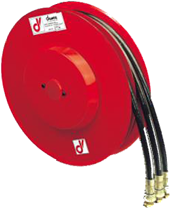
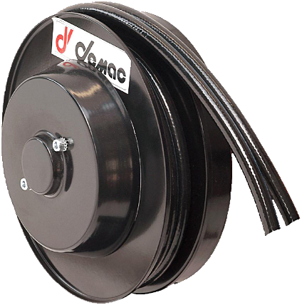
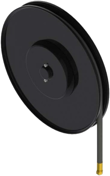
S1 single-spiral reel: one hydraulic hose from 5/16″ to 1″, 30 to 135 l/min depending on diameter. Twelve sizes with published data and 1.1 to 18 m usable length depending on configuration.
Number of lines
1 line
Hose diameter
5/16" - DN 8 to 1" - DN 25
High pressure
Up to 400 bar
Material
Painted steel

S1 Single Spiral reel — 1 hydraulic hose | DEMAC

Technical specifications

Technical specifications

Product type

Hose reel

Hose configuration

Single hose

Number of lines

1 line

Flow rate 30 l/min, 40 l/min, 60 l/min, 80 l/min, 135 l/min
Application

High-pressure hydraulics, Mobile machinery and cranes

Rewind mechanism

Automatic (spring rewind)

Material

Painted steel

Pressure 300 bar, 400 bar
Hose diameter 5/16" - DN 8, 3/8" - DN 10, 1/2" - DN 13, 5/8" - DN 16, 3/4" - DN 19, 1" - DN 25
Length range Up to 15 m, 15 to 30 m
ATEX zone

On request

Hose type

1SN, 2SC, 4SH, 4SP, B1, B3, T2

Maximum fluid temperature

80 °C

Equipment

Bare reel, Supplied with hoses

Technical drawings View technical drawings

The S1 Single Spiral is a spring-return reel for one hydraulic hose, from 5/16″ to 1″ depending on the part number. The 12 sizes with published data cover 1.1 to 18 m of usable length. The maximum flow rate depends on the diameter code: 30 to 135 l/min, not 135 l/min on every version.

Key features

  • One hydraulic line.
  • Maximum unwinding speed: 30 m/min.
  • 12 sizes with published data, side plates from 295 to 720 mm.
  • Separate lengths for each hose type.

Part number and replacement

S1D: right-hand; S1S: left-hand. Code .26 corresponds to 1″ on the standard part numbers on this page. Keep the full code and type XX.

Options

  • 300 bar as standard; 400 bar optional.
  • -20/+80 °C; -40/+80 °C optional.
  • Vertical downward travel: /VD.
  • ATEX II 2G execution on request.

Sizes and technical data

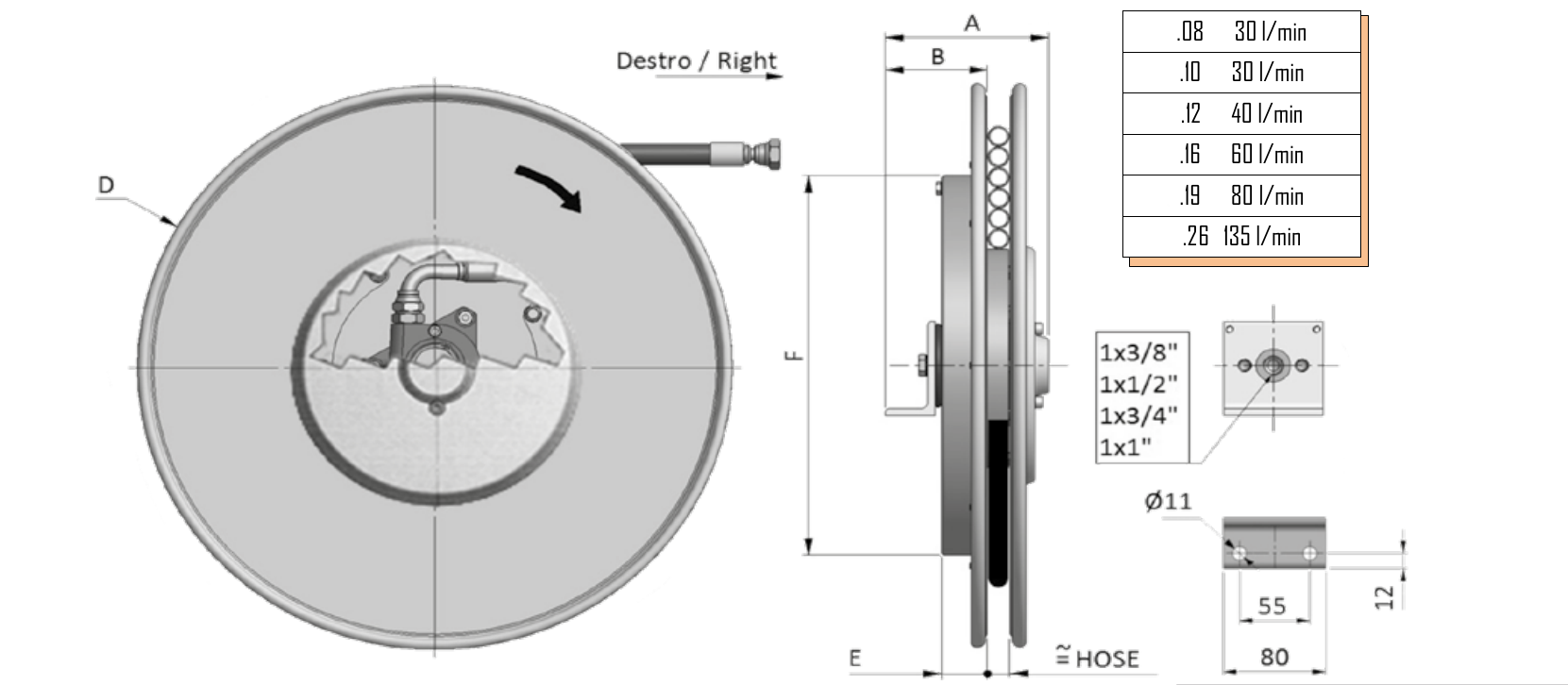
Flow rates by catalogue code, followed by dimensions in millimetres. Weights are not specified. For paired A/B values, the second applies to 1″. Size 650 also has specific dimensions for 5/8″ and 3/4″.

Diameter code Internal Ø Maximum flow rate
.08 5/16″ 30 l/min
.10 3/8″ 30 l/min
.12 1/2″ 40 l/min
.16 5/8″ 60 l/min
.19 3/4″ 80 l/min
.26 1″ 135 l/min
Model A B D (side plate) E F
S1D296 150 82 295 37 272
S1D321 150 82 325 37 272
S1D341 150 82 340 37 272
S1D370 150 82 370 37 322
S1D400 150 92 400 47 322
S1D420 190 92 420 47 322
S1D470 160 92 478 47 322
S1D520 160 / 201 92 / 122 520 47 422
S1D570 160 / 201¹ 92 / 122¹ 570 47 422
S1D600 160 / 201¹ 92 / 122¹ 620 47 422
S1D650 (.10/.12) 160 92 650 47 422
S1D650 (.16/.19) 180 102 650 47 422
S1D650.26 201 122 650 47 422
S1D700 160 / 201¹ 92 / 122¹ 720 47 422

Part numbers and lengths

Lengths in metres. The reinforced column applies to 4SP, or 4SH for 1″. Availability by type/diameter must be confirmed; do not transfer a length from one hose construction to another.

Part number Internal Ø B1/T2/B3/1SN/2SC: total (m) B1/T2/B3/1SN/2SC: usable (m) 4SP / 4SH: total 4SP / 4SH: usable
S1D296.08.XX 5/16″ 1.4 1.1
S1D296.10.XX 3/8″ 1.5 1.2
S1D321.08.XX 5/16″ 2.3 2.0
S1D321.10.XX 3/8″ 2.4 2.1
S1D341.08.XX 5/16″ 3.3 3.0
S1D341.10.XX 3/8″ 2.4 2.1
S1D341.12.XX 1/2″ 2.5 2.2
S1D370.08.XX 5/16″ 4.4 4.1
S1D370.10.XX 3/8″ 3.5 3.2
S1D370.12.XX 1/2″ 3.6 3.3
S1D400.08.XX 5/16″ 5.7 5.4
S1D400.10.XX 3/8″ 4.6 4.3
S1D400.12.XX 1/2″ 3.6 3.3
S1D420.08.XX 5/16″ 6.7 6.2
S1D420.10.XX 3/8″ 5.7 5.2
S1D420.12.XX 1/2″ 4.8 4.3
S1D420.16.XX 5/8″ 2.6 2.1
S1D420.19.XX 3/4″ 2.6 2.1
S1D470.08.XX 5/16″ 8.4 7.9
S1D470.10.XX 3/8″ 7.3 6.8
S1D470.12.XX 1/2″ 6.3 5.8 3.6 3.1
S1D470.16.XX 5/8″ 4.0 3.5 4.0 3.5
S1D470.19.XX 3/4″ 2.7 2.2 3.0 2.5
S1D520.08.XX 5/16″ 9.9 9.4
S1D520.10.XX 3/8″ 8.9 8.4
S1D520.12.XX 1/2″ 7.9 7.4 5.0 4.5
S1D520.16.XX 5/8″ 5.0 4.5 4.5 4.0
S1D520.19.XX 3/4″ 4.2 3.9 4.2 3.7
S1D520.26.XX 1″ 2.8 2.5 2.4 1.9
S1D570.10.XX 3/8″ 10.6 10.1
S1D570.12.XX 1/2″ 9.7 9.2 6.7 6.2
S1D570.16.XX 5/8″ 5.7 5.4 6.0 5.5
S1D570.19.XX 3/4″ 5.3 4.8 5.9 5.4
S1D570.26.XX 1″ 4.0 3.7 4.0 3.5
S1D600.10.XX 3/8″ 12.3 11.8
S1D600.12.XX 1/2″ 11.4 10.9 8.5 8.0
S1D600.16.XX 5/8″ 7.5 7.0 7.5 7.0
S1D600.19.XX 3/4″ 7.0 6.5 7.3 6.8
S1D600.26.XX 1″ 6.0 5.7 4.0 3.5
S1D650.10.XX 3/8″ 14.3 13.8
S1D650.12.XX 1/2″ 11.8 11.3 10.5 10.0
S1D650.16.XX 5/8″ 9.4 9.1 9.0 8.5
S1D650.19.XX 3/4″ 7.8 7.5 7.3 6.8
S1D650.26.XX 1″ 6.3 6.0 5.8 5.3
S1D700.10.XX 3/8″ 18.5 18.0
S1D700.12.XX 1/2″ 15.0 14.5 12.6 12.1
S1D700.16.XX 5/8″ 13.0 12.5 11.5 11.0
S1D700.19.XX 3/4″ 9.8 9.5 10.0 9.5
S1D700.26.XX 1″ 8.0 7.5 7.9 7.4

¹ In the dimensions table, the second value applies to 1″. The maximum usable length of 18 m is listed for S1D700.10.XX in 3/8″; in 1″, S1D700.26.XX has 7.5 m usable length in the first columns and 7.4 m with 4SH.

On request only, with no numerical data shown: S1D800.26.19.XX, S1D800.26.25.XX, S1D900.26.26.XX and S1D1000.26.25.XX. Unusual codes are kept as printed; request confirmation without automatically standardising them.

The permissible pressure of the supplied assembly must respect the limits of the reel, hose and connections. Specify the fluid, its temperature, the flow rate and working pressure to validate the equipped part number; the pressure rating of the reel alone does not guarantee that of every hose combination.

Pressure ratings of hoses alone

TU1 catalogue reference data: pressure ratings of the hose alone, in bar. These values are not the guaranteed pressure rating of the equipped reel. The final configuration must respect the limits of all its components; the table below does not establish that every combination is available in every size.

Internal Ø Hose type Pressure rating of hose alone (bar)
1″ 1SN 88
1″ 2SC 210
1″ 4SH 380
5/16″ 1SN 215
5/16″ B1 250
5/16″ T2 400
5/16″ 2SC 350
3/8″ 1SN 180
3/8″ B1 225
3/8″ T2 330
3/8″ 2SC 330
3/8″ B3 420
3/8″ 4SP 445
1/2″ 1SN 160
1/2″ B1 190
1/2″ T2 260
1/2″ 2SC 275
1/2″ B3 350
1/2″ 4SP 415
5/8″ 1SN 130
5/8″ T2 220
5/8″ 2SC 250
5/8″ 4SP 360
3/4″ 1SN 105
3/4″ T2 150
3/4″ 2SC 215
3/4″ 4SP 350

Preparing a replacement

To replace a reel, send the full part number and a photograph of the nameplate, mounting details, right/left-hand version, working position, fittings and usable length. Request the manual for the exact version before installation or servicing.

Compare the S1 Compact for smaller capacities and the M1 for multi-spiral winding. For longer capacities with one hose up to 1″, see the A1.25 and its own dimensions. See the DEMAC technical catalogues.

Unsure about the part number?

Tell us the number of lines, hose diameter, working pressure and flow rate, usable length and the machine to be equipped.

Request a quote

Product:

Enter your part number, quantity or required specifications. Fields marked * are required.

Enquiry type *
Your requirements *
If you know the part number, provide the full code and quantity. For a replacement, send the reel's serial number, which is needed to identify the unit to be replaced. It is shown on the identification label; if this is unavailable, see the illustrated locations on the Contact page. For a new configuration, specify the number of hoses or cables, usable length and available technical data. Tell us what you know; we will help you complete the details.
Company
Name
Email address *
Telephone
Attach a file
Maximum file size: 10 MB
For a replacement: a clear photo of the label showing the serial number, plus a view of the reel or its installation. If the label is unavailable, see the illustrated locations on the Contact page. You may also attach a drawing or part number. Up to 3 files, maximum 10 MB per file.

Open the form on the Contact page

Nous appeler