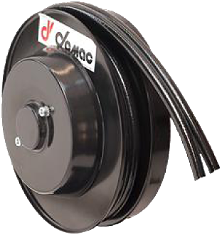
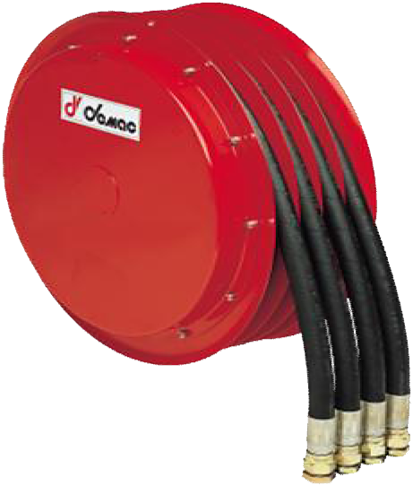
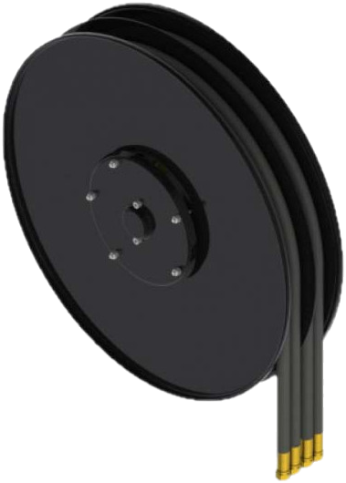
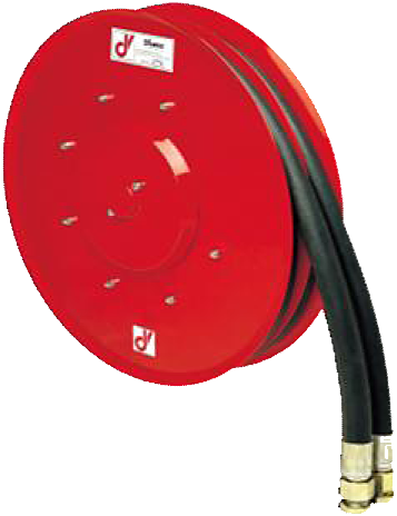
The AG/F is a spring-return reel for two hydraulic lines in a twin hose, with flange mounting. Its 17 sizes offer 1.2 to 39 m usable length depending on diameter and part number. The flange and some overall dimensions vary: compare the complete mounting before replacement.
Key features
- Two hydraulic lines in a twin hose.
- Maximum flow rate: 40 l/min.
- Maximum unwinding speed: 30 m/min.
- Diameters: 1/4″ to 1/2″.
Part number and replacement
AGD: right-hand; AGS: left-hand. Suffix /F identifies flange mounting. Send the full part number, a photograph of the nameplate and the mounting drawing.
Options
- 300 bar as standard; 400 bar optional.
- -20/+80 °C; -40/+80 °C optional.
- Vertical downward travel:
/VD.
- ATEX II 2G execution on request.
Sizes and dimensions
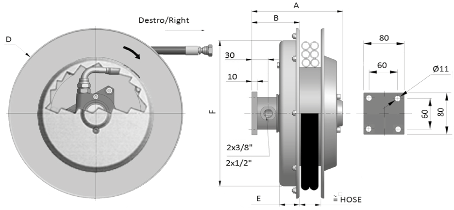
Dimensions in millimetres, weights without hose. The model size does not replace the actual side plate dimension D. Rows that distinguish a diameter reflect the variants in the manufacturer’s drawing.
| Right-hand model |
A (mm) |
B (mm) |
D (mm) |
E (mm) |
F (mm) |
Weight without hoses (kg) |
| AGD270/F |
166 |
87 |
275 |
30 |
270 |
10 |
| AGD296/F |
166 / 212¹ |
87 |
295 |
35 |
291 |
13 |
| AGD321/F |
166 / 212¹ |
87 |
325 |
37 |
272 |
14 |
| AGD341/F |
166 / 212¹ |
87 |
340 |
37 |
272 |
14 |
| AGD370/F |
166 / 212¹ |
87 |
370 |
37 |
272 |
14.5 |
| AGD400/F |
166 / 212¹ |
87 |
400 |
37 |
322 |
15 |
| AGD420/F |
176 / 212¹ |
97 |
420 |
47 |
322 |
19 |
| AGD470/F |
176 / 212¹ |
97 |
478 |
47 |
322 |
21 |
| AGD520/F |
176 / 212¹ |
97 |
520 |
47 |
322 |
23 |
| AGD570/F |
176 / 212¹ |
97 |
570 |
47 |
322 (.06, .08) / 422 (.10, .12) |
28 |
| AGD600/F |
176 / 212¹ |
107 |
620 |
47 |
422 |
34 |
| AGD650/F |
176 / 212¹ |
107 |
650 |
47 |
422 |
37 |
| AGD700.06.XX/F |
206 |
127 |
720 |
57 |
532 |
40 |
| AGD700.08 or .10.XX/F |
176 |
107 |
720 |
47 |
532 |
40 |
| AGD700.12.XX/F |
212 |
107 |
720 |
47 |
532 |
40 |
| AGD800/F |
186 / 227¹ |
107 |
820 |
57 |
532 |
47 |
| AGD900/F |
227 |
107 |
920 |
67 |
532 |
60 |
| AGD950/F |
227 |
107 |
950 |
67 |
687 |
70 |
| AGD1000/F |
227 |
107 |
To be confirmed² |
67 |
687 |
75 |
¹ The second A value applies to the 1/2″ hose. ² The catalogue shows “###” in the AGD1000/F dimension D cell: request the dimensioned drawing for this part number. The flange drawing shows four Ø 11 mm holes on 60 mm square centres, with an 80 mm overall size. PDF and STEP technical drawings on request.
Part numbers and lengths
Lengths in metres, distinguishing total and usable length. Hose types shown are R7, R8, B1, B2 and T2; have the combination of type, diameter and connection confirmed for the equipped part number.
| Part number |
Internal Ø |
Total length |
Usable length |
| AGD270.06.XX/F |
1/4″ |
4.0 |
3.7 |
| AGD270.08.XX/F |
5/16″ |
3.2 |
2.9 |
| AGD270.10.XX/F |
3/8″ |
2.8 |
2.5 |
| AGD296.06.XX/F |
1/4″ |
3.0 |
2.7 |
| AGD296.08.XX/F |
5/16″ |
2.3 |
2.0 |
| AGD296.10.XX/F |
3/8″ |
2.3 |
2.0 |
| AGD296.12.XX/F |
1/2″ |
1.5 |
1.2 |
| AGD321.06.XX/F |
1/4″ |
4.0 |
3.7 |
| AGD321.08.XX/F |
5/16″ |
3.2 |
2.9 |
| AGD321.10.XX/F |
3/8″ |
3.3 |
3.0 |
| AGD321.12.XX/F |
1/2″ |
2.5 |
2.2 |
| AGD341.06.XX/F |
1/4″ |
5.0 |
4.7 |
| AGD341.08.XX/F |
5/16″ |
4.2 |
3.9 |
| AGD341.10.XX/F |
3/8″ |
4.0 |
3.7 |
| AGD341.12.XX/F |
1/2″ |
2.5 |
2.2 |
| AGD370.06.XX/F |
1/4″ |
6.0 |
5.7 |
| AGD370.08.XX/F |
5/16″ |
5.3 |
5.0 |
| AGD370.10.XX/F |
3/8″ |
4.5 |
4.2 |
| AGD370.12.XX/F |
1/2″ |
3.5 |
3.2 |
| AGD400.06.XX/F |
1/4″ |
7.3 |
7.0 |
| AGD400.08.XX/F |
5/16″ |
6.5 |
6.2 |
| AGD400.10.XX/F |
3/8″ |
5.6 |
5.3 |
| AGD400.12.XX/F |
1/2″ |
4.5 |
4.2 |
| AGD420.06.XX/F |
1/4″ |
8.6 |
8.1 |
| AGD420.08.XX/F |
5/16″ |
8.0 |
7.5 |
| AGD420.10.XX/F |
3/8″ |
6.7 |
6.2 |
| AGD420.12.XX/F |
1/2″ |
4.7 |
4.2 |
| AGD470.06.XX/F |
1/4″ |
11.5 |
11.0 |
| AGD470.08.XX/F |
5/16″ |
10.0 |
9.5 |
| AGD470.10.XX/F |
3/8″ |
9.5 |
9.0 |
| AGD470.12.XX/F |
1/2″ |
7.5 |
7.0 |
| AGD520.06.XX/F |
1/4″ |
14.5 |
14.0 |
| AGD520.08.XX/F |
5/16″ |
12.5 |
12.0 |
| AGD520.10.XX/F |
3/8″ |
11.2 |
10.7 |
| AGD520.12.XX/F |
1/2″ |
9.0 |
8.5 |
| AGD570.06.XX/F |
1/4″ |
17.5 |
17.0 |
| AGD570.08.XX/F |
5/16″ |
15.5 |
15.0 |
| AGD570.10.XX/F |
3/8″ |
13.5 |
13.0 |
| AGD570.12.XX/F |
1/2″ |
10.7 |
10.2 |
| AGD600.06.XX/F |
1/4″ |
21.0 |
20.5 |
| AGD600.08.XX/F |
5/16″ |
17.0 |
16.5 |
| AGD600.10.XX/F |
3/8″ |
16.0 |
15.5 |
| AGD600.12.XX/F |
1/2″ |
12.5 |
12.0 |
| AGD650.06.XX/F |
1/4″ |
22.5 |
22.0 |
| AGD650.08.XX/F |
5/16″ |
19.5 |
19.0 |
| AGD650.10.XX/F |
3/8″ |
17.5 |
17.0 |
| AGD650.12.XX/F |
1/2″ |
14.5 |
14.0 |
| AGD700.06.XX/F |
1/4″ |
27.0 |
26.5 |
| AGD700.08.XX/F |
5/16″ |
22.0 |
21.5 |
| AGD700.10.XX/F |
3/8″ |
20.0 |
19.5 |
| AGD700.12.XX/F |
1/2″ |
16.0 |
15.5 |
| AGD800.08.XX/F |
5/16″ |
30.0 |
29.0 |
| AGD800.10.XX/F |
3/8″ |
26.0 |
25.0 |
| AGD800.12.XX/F |
1/2″ |
21.0 |
20.0 |
| AGD900.08.XX/F |
5/16″ |
38.0 |
37.0 |
| AGD900.10.XX/F |
3/8″ |
34.0 |
33.0 |
| AGD900.12.XX/F |
1/2″ |
28.0 |
27.0 |
| AGD950.10.XX/F |
3/8″ |
37.0 |
36.0 |
| AGD950.12.XX/F |
1/2″ |
31.0 |
30.0 |
| AGD1000.10.XX/F |
3/8″ |
40.0 |
39.0 |
| AGD1000.12.XX/F |
1/2″ |
35.0 |
34.0 |
XX denotes the hose type; AGD296.06.R7/F illustrates how to read the code. For a bare reel, explicitly specify “without hose”. Do not omit /F when searching or requesting a replacement.
The permissible pressure of the supplied assembly must respect the limits of the reel, hose and connections. Specify the fluid, its temperature, the flow rate and working pressure to validate the equipped part number; the pressure rating of the reel alone does not guarantee that of every hose combination.
Pressure ratings of hoses alone
TU2 catalogue reference data: pressure ratings of the hose alone, in bar. These values are not the guaranteed pressure rating of the equipped reel. The final configuration must respect the limits of all its components; the table below does not establish that every combination is available in every size.
| Internal Ø |
Hose type |
Pressure rating of hose alone (bar) |
| 1/4″ |
R7 |
210 |
| 1/4″ |
B1 |
310 |
| 1/4″ |
R8 |
350 |
| 1/4″ |
T2 |
400 |
| 1/4″ |
B2 |
425 |
| 5/16″ |
R7 |
190 |
| 5/16″ |
B1 |
250 |
| 5/16″ |
R8 |
300 |
| 5/16″ |
T2 |
400 |
| 3/8″ |
R7 |
160 |
| 3/8″ |
B1 |
225 |
| 3/8″ |
R8 |
280 |
| 3/8″ |
T2 |
330 |
| 3/8″ |
B2 |
350 |
| 1/2″ |
B1 |
190 |
| 1/2″ |
R8 |
245 |
| 1/2″ |
T2 |
260 |
| 1/2″ |
B2 |
310 |
Preparing a replacement
To replace a reel, send the full part number and a photograph of the nameplate, mounting details, right/left-hand version, working position, fittings and usable length. Request the manual for the exact version before installation or servicing.
For a standard mounting bracket, compare the AG; for two separate flange-mounted hoses, compare the A2/F. Moving between families requires verification of the hose configuration, travel and mounting drawing. See the DEMAC technical catalogues.